Updated 2/20/18 - Photos added from 2006
Layout Progress - 1st Decade
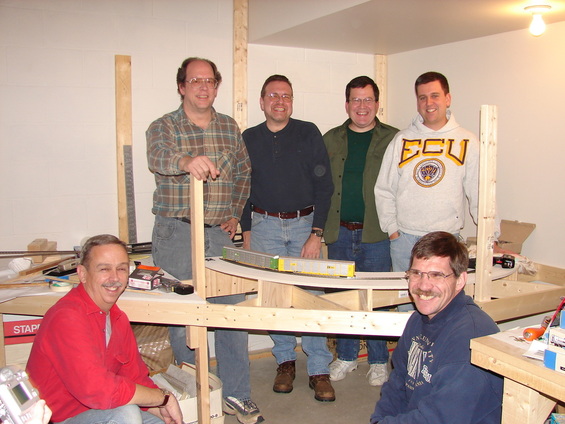
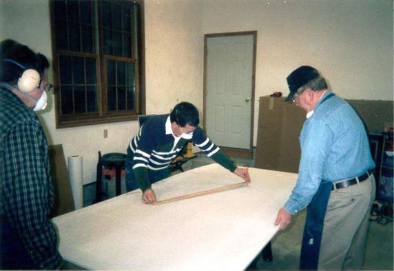
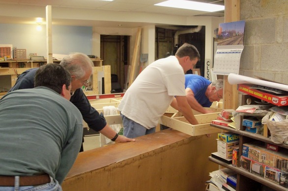
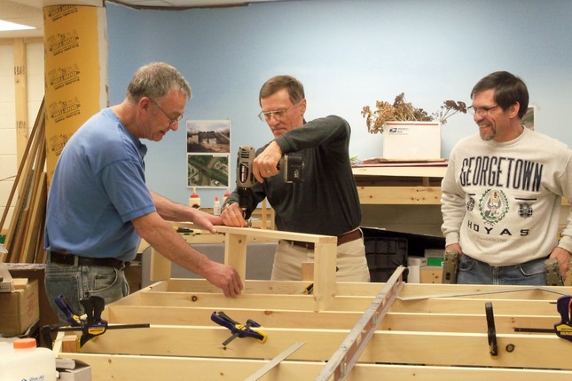
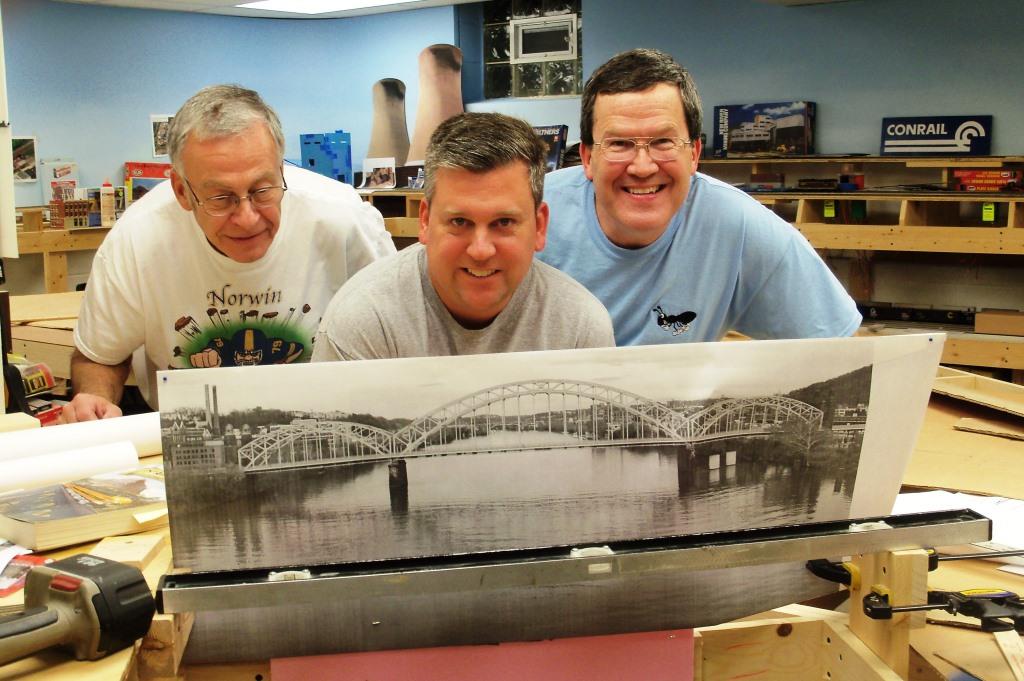
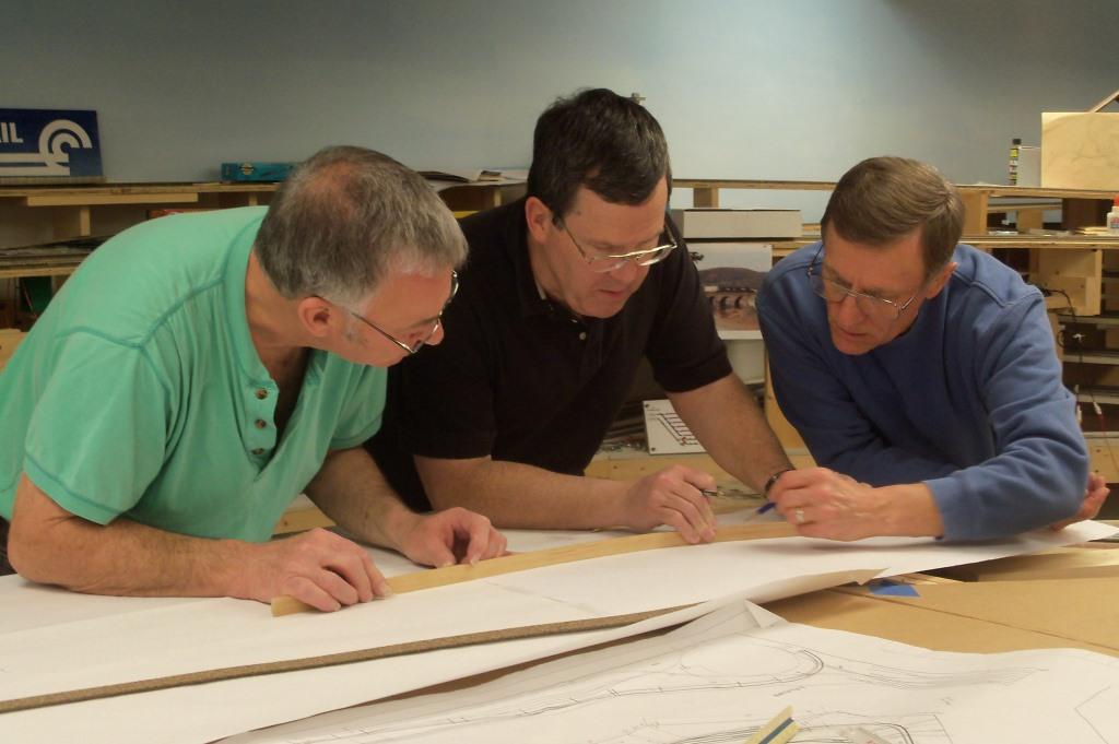
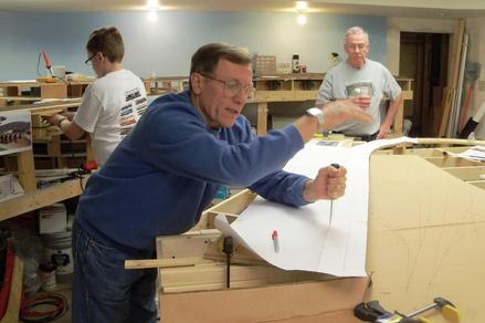
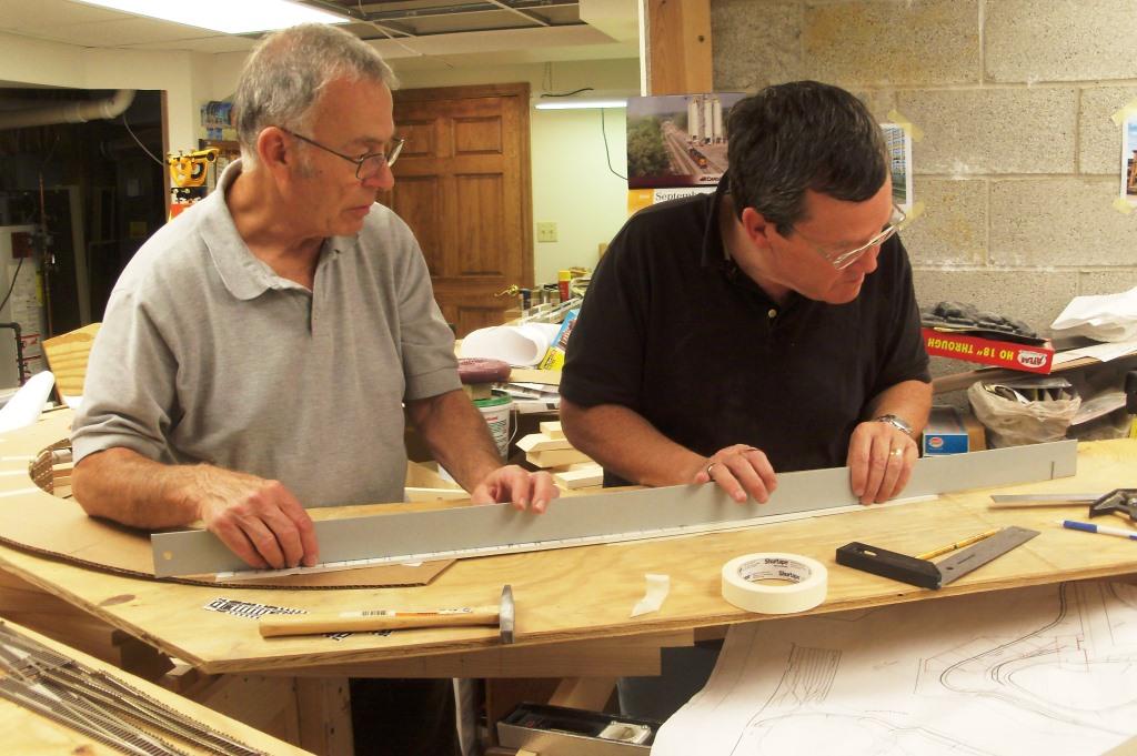
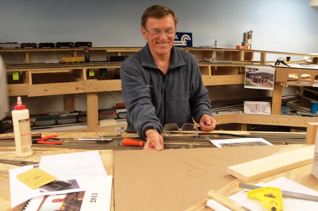
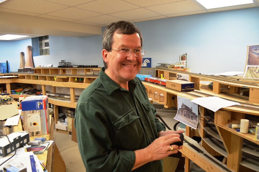
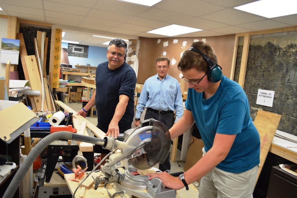
Andy and Charlie want to thank everyone who has helped over the years for their hard work and dedication to the PML. From left: Bruce Light, Tom Gaus, Greg Cinna, Bob Dengler and Gary Gillespie. And to those not pictured Bob Evans, Jerry Kyslinger, Paul Metzger, Kent Miller, Dan Grieco, Jim Montgomery, Howard Heltman, Mike Rabbit, Kevin Sapanara and Patrick Altdorfer. Thanks for Everything!
My father built my brother and me an HO scale train layout when I was a child, and I enjoyed detailing the simple 4 x 8 foot layout until my early teens. After graduating from college and having my railroad interest reawakened, I dug out this layout and bought some up-to-date motive power and rolling stock. Night school, my career and a relocation sidelined model railroading for most of a decade, but in 1999 I discovered that several of my co-workers in the civil engineering profession were also modelers and we had the nucleus to plan and build a model railroad in my basement. We joined the local division of the NMRA (Mid-Central Region, Keystone Division 2), which gave us an opportunity to visit a number of local club and home layouts, many of which provided us with ideas and inspiration.
I began planning a layout using a scale drawing of the basement (1 inch = 1 foot), which was a good size for sketching and allowed the use of an HO scale track planning template purchased at a local hobby shop. My initial goal was to model the Conrail main line from Wilkinsburg to Pitcairn, the area that I had known as a boy. However, after operating on several home layouts in our area (Ken Hanawalt and Carl Volkwein’s Turtle Creek Railroad; Bob Prehoda’s Huntingdon Northern; and John Scott’s Johnstown, Maryannville and Scottdale), I soon realized that realistic operations required a point of origin and a destination for freight traffic, some of which might even be off the layout. My attempt to model one stretch of track as I had originally planned would severely restrict realistic operations. I needed to “think big” and use selective compression in order to model an entire division, rather than just a few towns.
My next layout sketch went further – Wilkinsburg to Latrobe. However, through an addition to our home, our real estate agents were able to acquire additional right-of-way in the basement and “real world” operations still dictated a larger area to be modeled. There are no significant interchange points on the Conrail main line between Greensburg and Latrobe, so I reached further east and decided that Johnstown should be the eastern-most city modeled on the layout. This would allow an interchange with the Chessie System (now CSX) at Johnstown. The two areas dedicated to the layout measure roughly 16’ x 20’ and 13’ x 25’, together forming an “L”. A small area under the stairs can serve as a dispatch office.
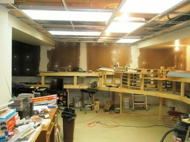
Looking towards the western end of the layout, again there are no significant interchange points at or near Wilkinsburg, so it was decided to extend the layout west to include downtown Pittsburgh and a bit beyond. This gives us the opportunity to model a bit of urban scenery, which I enjoy, including the magnificent Pennsylvania Railroad Station in downtown Pittsburgh. While I would have loved to model Conway Yard, located perhaps 20 miles northwest of Pittsburgh, I could not do it justice given my space constraints. Instead, the layout will terminate at its western end at Island Avenue Yard, a smaller interchange yard located on Pittsburgh’s North Side. Although not as busy as it was in the glory days of the Pennsylvania Railroad, Island Avenue Yard today serves as the interchange point with the Allegheny Valley Railroad.
I began planning a layout using a scale drawing of the basement (1 inch = 1 foot), which was a good size for sketching and allowed the use of an HO scale track planning template purchased at a local hobby shop. My initial goal was to model the Conrail main line from Wilkinsburg to Pitcairn, the area that I had known as a boy. However, after operating on several home layouts in our area (Ken Hanawalt and Carl Volkwein’s Turtle Creek Railroad; Bob Prehoda’s Huntingdon Northern; and John Scott’s Johnstown, Maryannville and Scottdale), I soon realized that realistic operations required a point of origin and a destination for freight traffic, some of which might even be off the layout. My attempt to model one stretch of track as I had originally planned would severely restrict realistic operations. I needed to “think big” and use selective compression in order to model an entire division, rather than just a few towns.
My next layout sketch went further – Wilkinsburg to Latrobe. However, through an addition to our home, our real estate agents were able to acquire additional right-of-way in the basement and “real world” operations still dictated a larger area to be modeled. There are no significant interchange points on the Conrail main line between Greensburg and Latrobe, so I reached further east and decided that Johnstown should be the eastern-most city modeled on the layout. This would allow an interchange with the Chessie System (now CSX) at Johnstown. The two areas dedicated to the layout measure roughly 16’ x 20’ and 13’ x 25’, together forming an “L”. A small area under the stairs can serve as a dispatch office.
Looking towards the western end of the layout, again there are no significant interchange points at or near Wilkinsburg, so it was decided to extend the layout west to include downtown Pittsburgh and a bit beyond. This gives us the opportunity to model a bit of urban scenery, which I enjoy, including the magnificent Pennsylvania Railroad Station in downtown Pittsburgh. While I would have loved to model Conway Yard, located perhaps 20 miles northwest of Pittsburgh, I could not do it justice given my space constraints. Instead, the layout will terminate at its western end at Island Avenue Yard, a smaller interchange yard located on Pittsburgh’s North Side. Although not as busy as it was in the glory days of the Pennsylvania Railroad, Island Avenue Yard today serves as the interchange point with the Allegheny Valley Railroad.
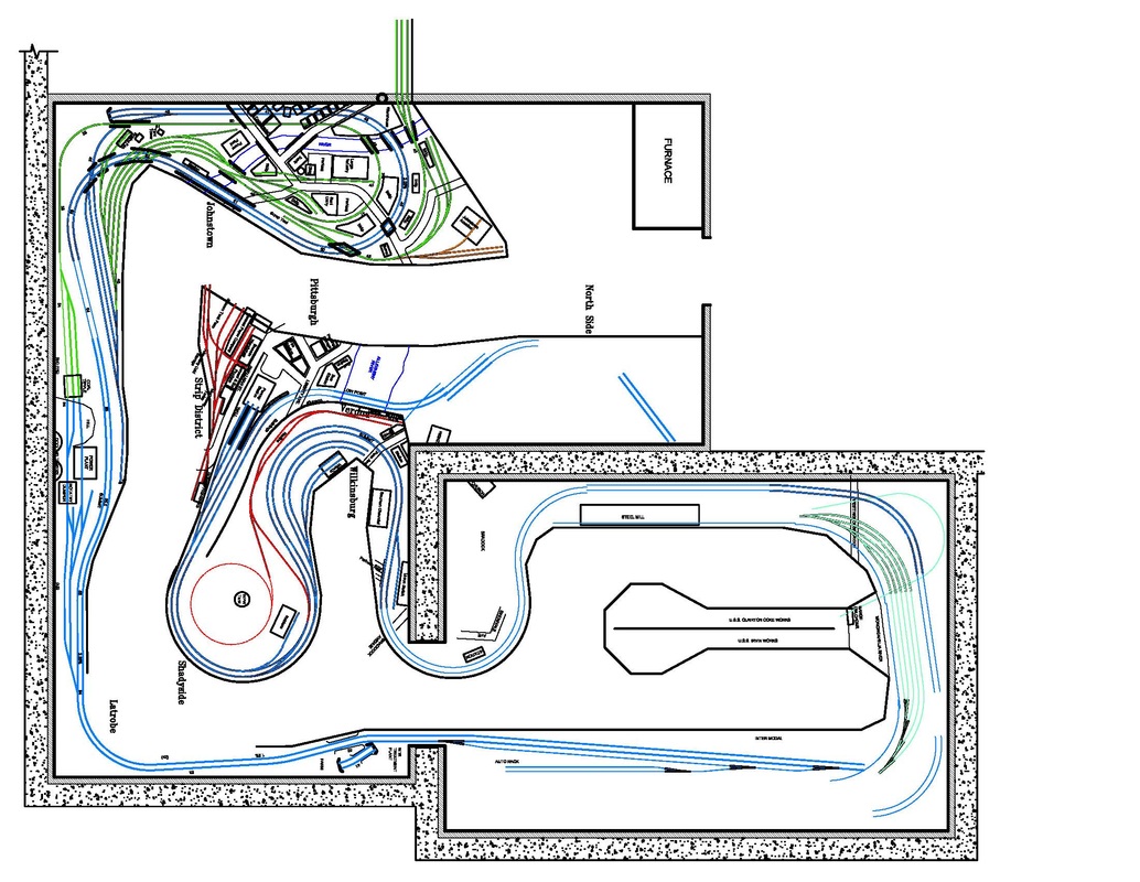
This was an early track plan that has since been revised. The rectangular room is the addition. Blue is CR track, green is Chessie, red is AVR and grey is URR. Click to enlarge.
|
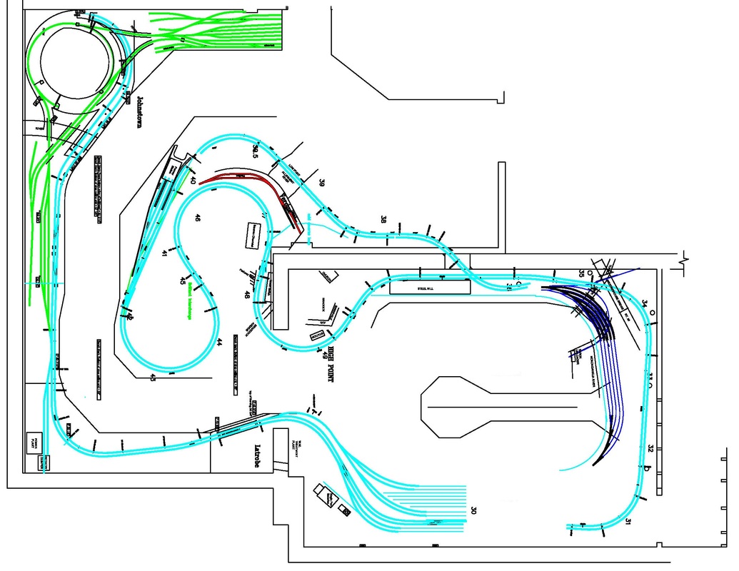
This is the current track plan. The Johnstown helix was pushed into the corner to improve the aisleway. Light blue is CR, green is Chessie, red is AVR and dark blue is URR. Click to enlarge
|
2006
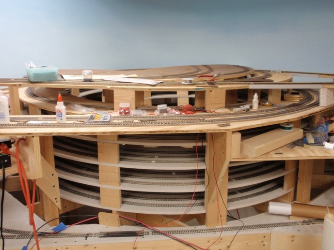
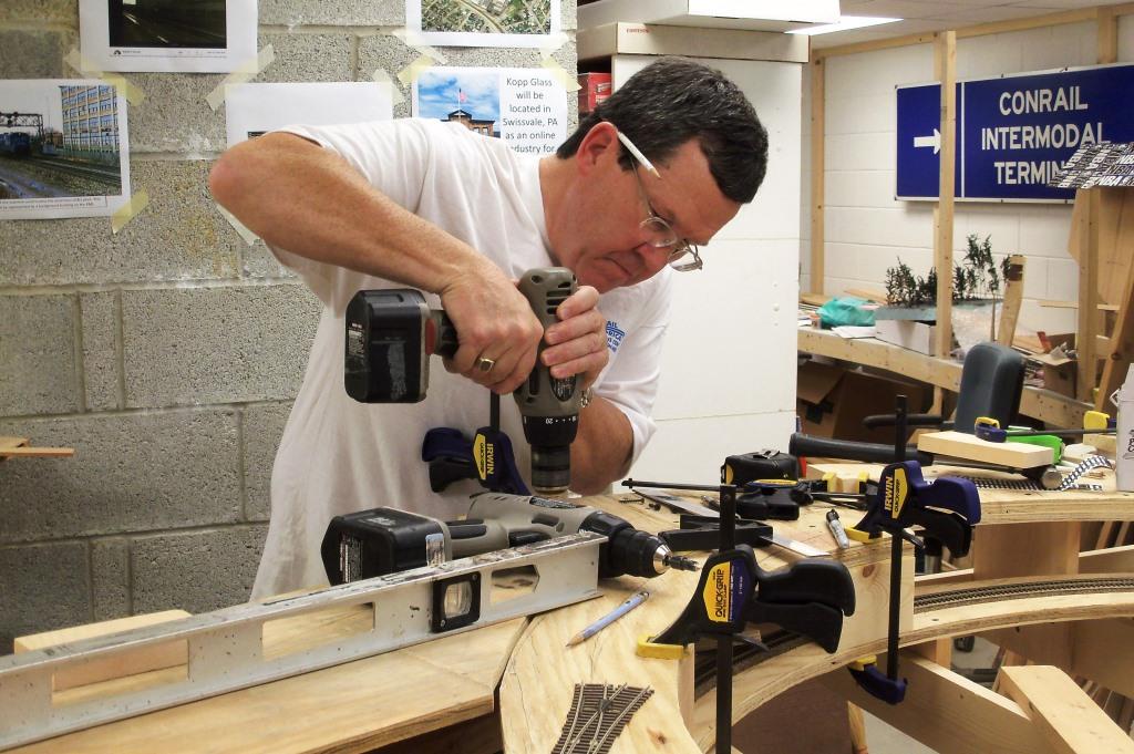
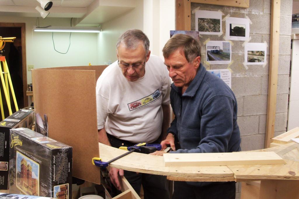
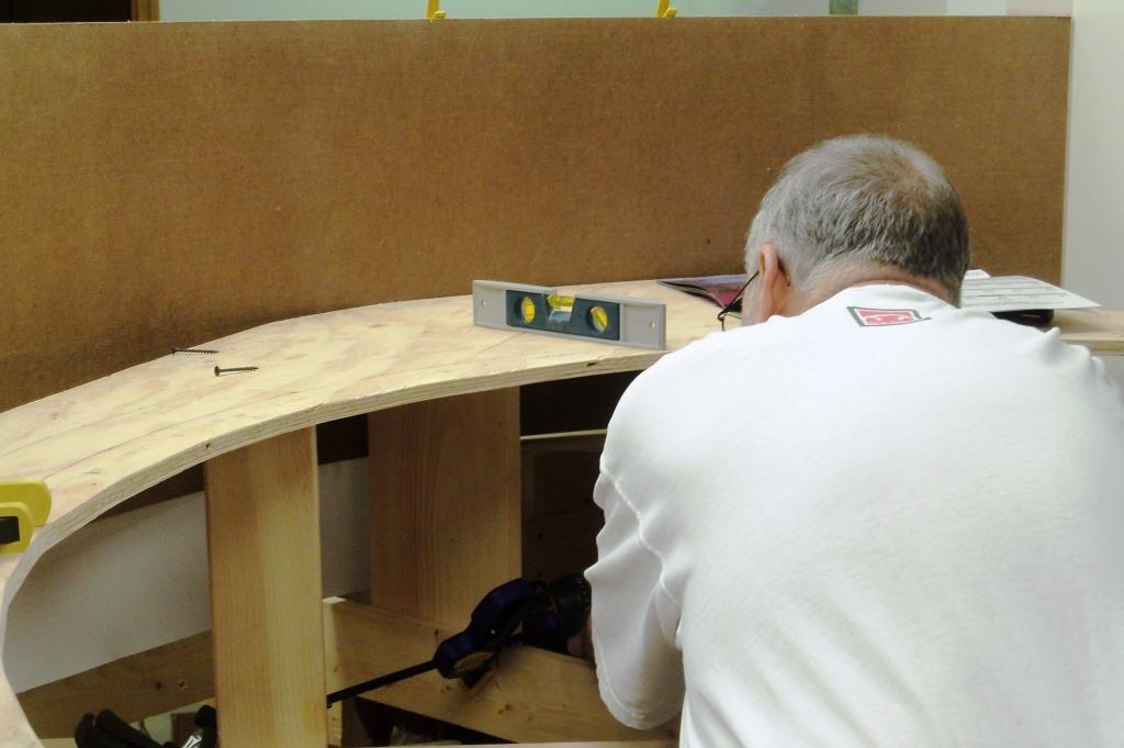
In 2006 construction was started on the helix, a 4.5 revolution spiral to get to the second level. Working one night a month, the helix took about a year to complete because everything had to be just right on the first level in order for the rest to work out.
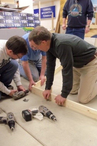
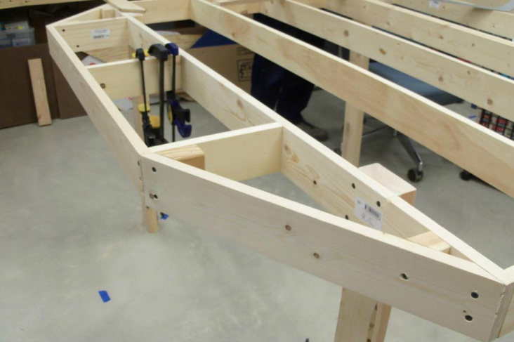
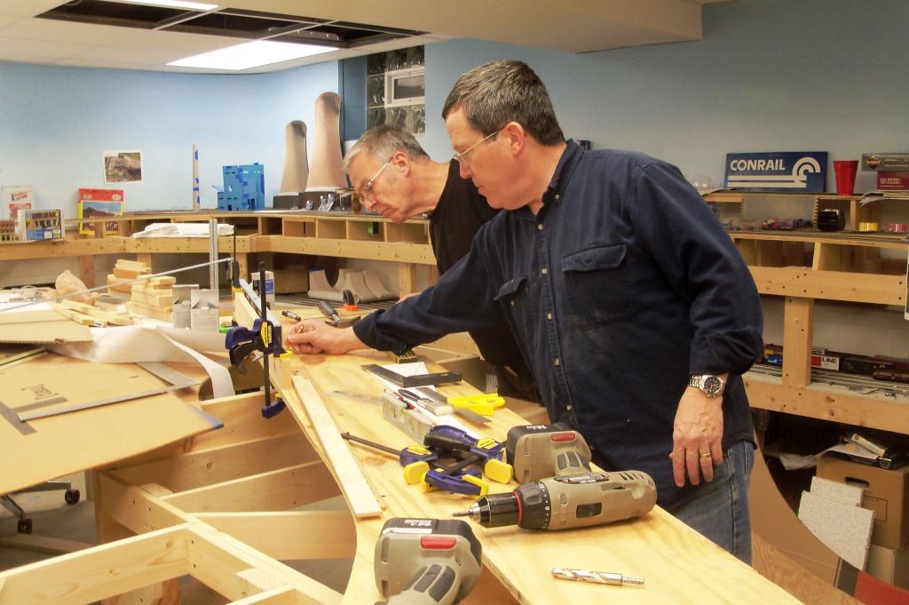
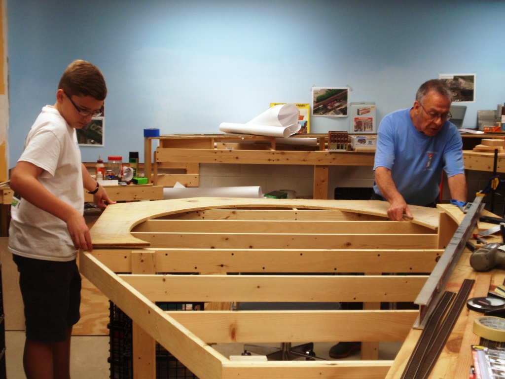
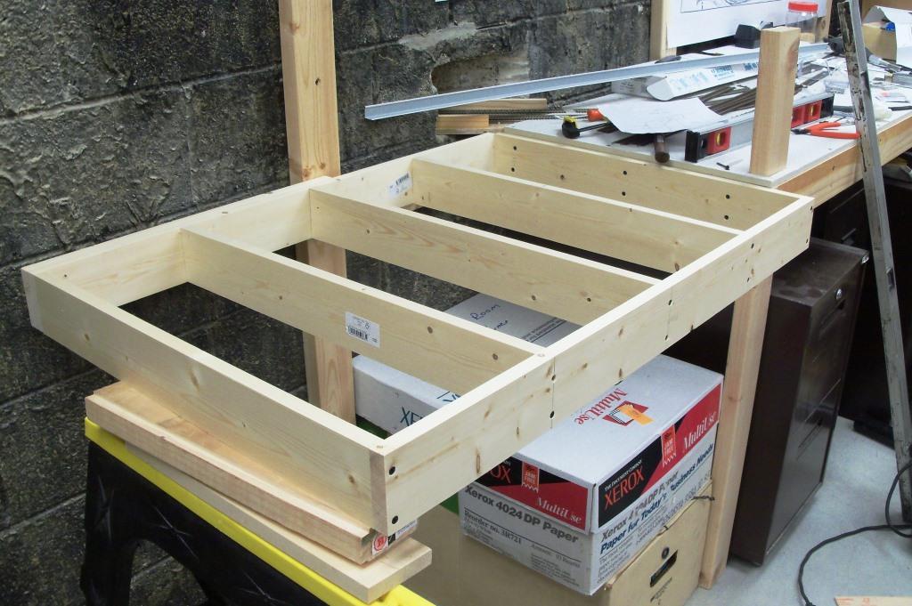
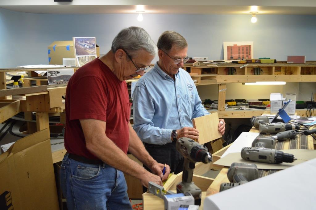
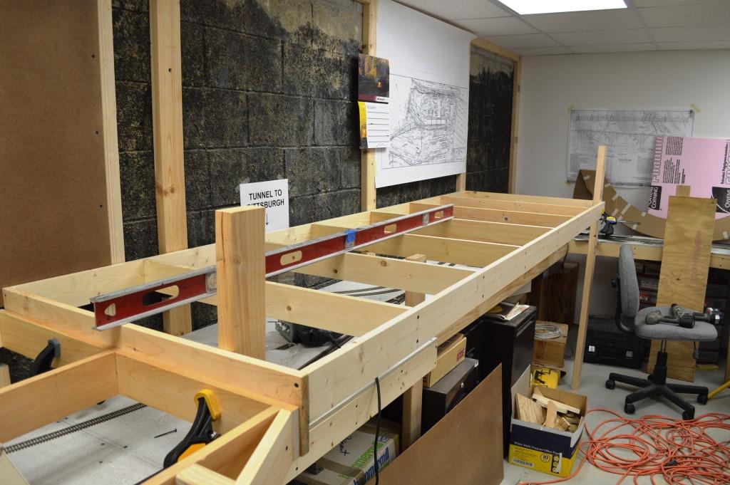
Kent and Gary working on a section of the first piece of benchwork.
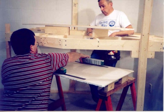
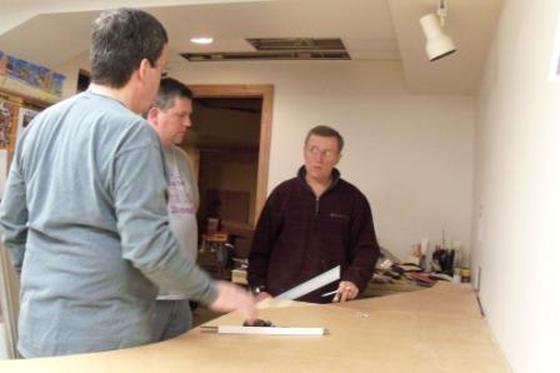
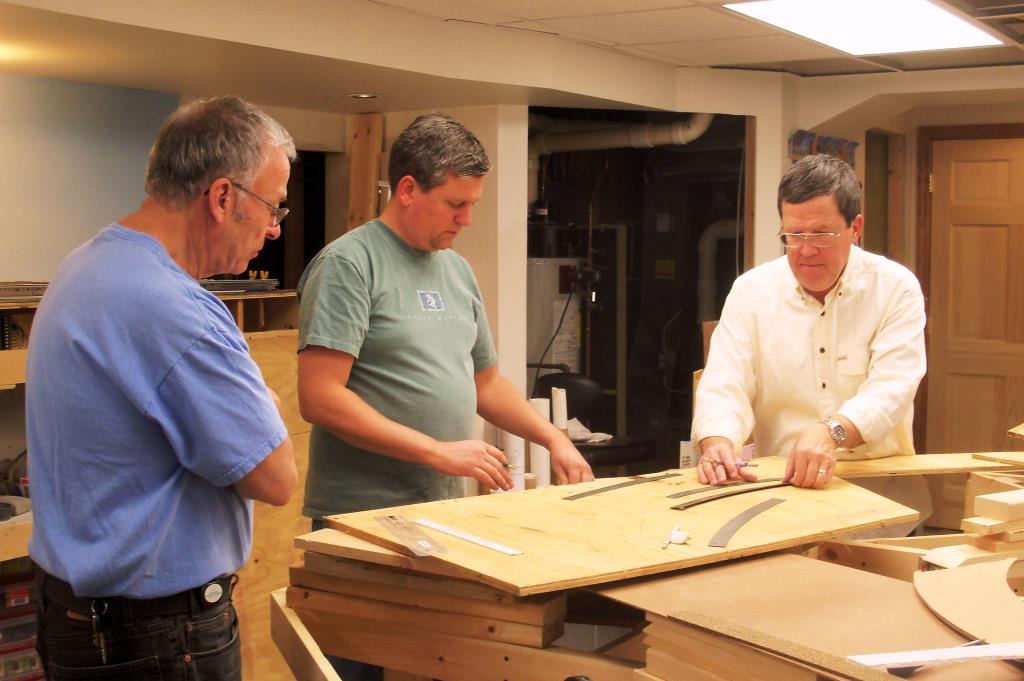
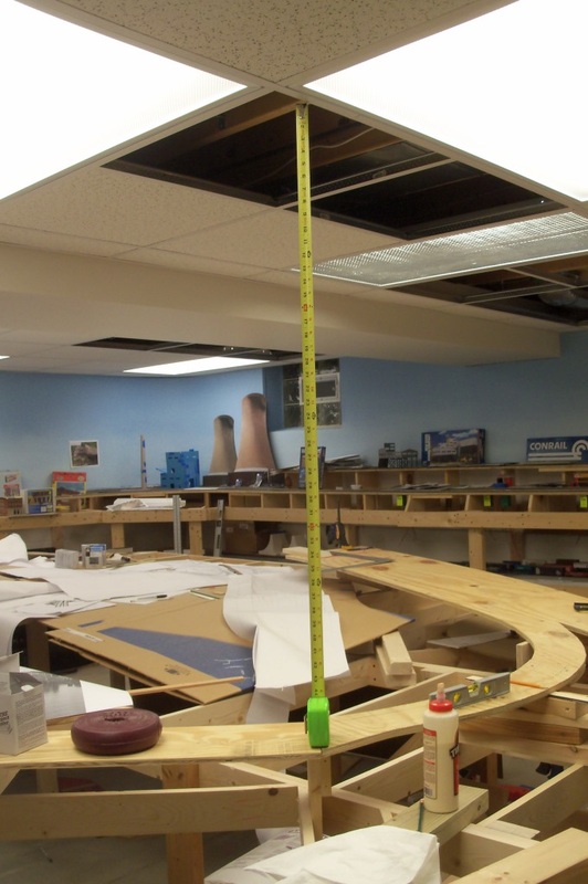
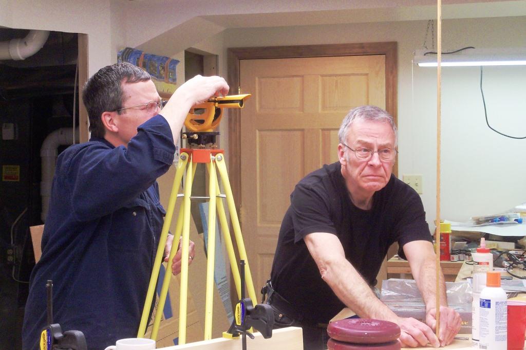
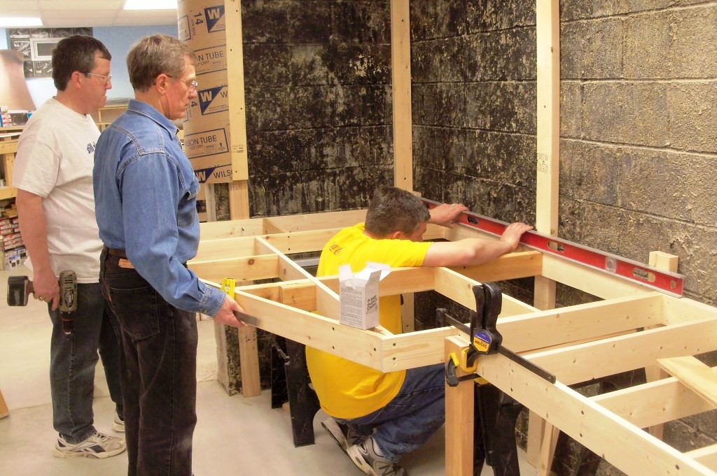
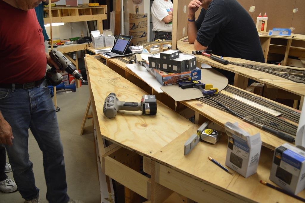
Andy and Bruce are testing how far you can reach to determine the staging yard height.
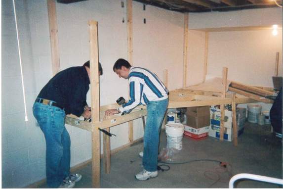
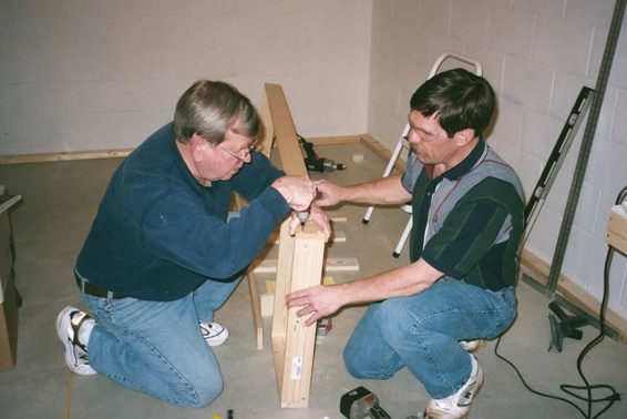
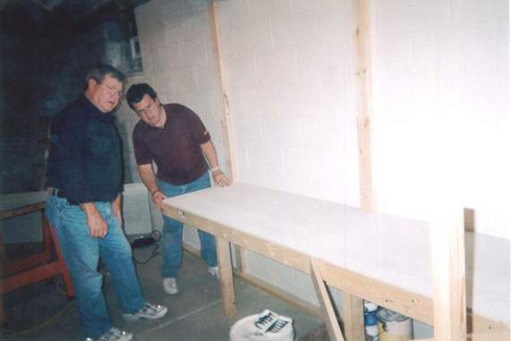
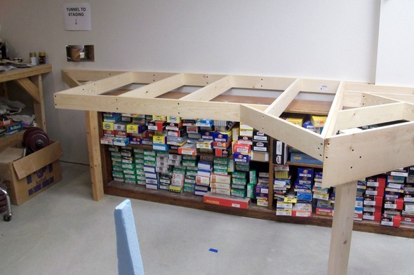
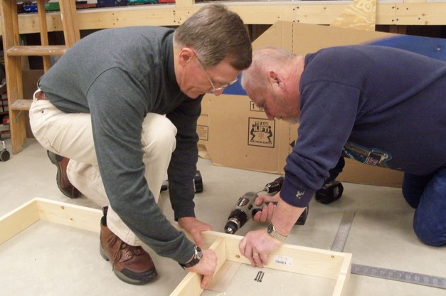
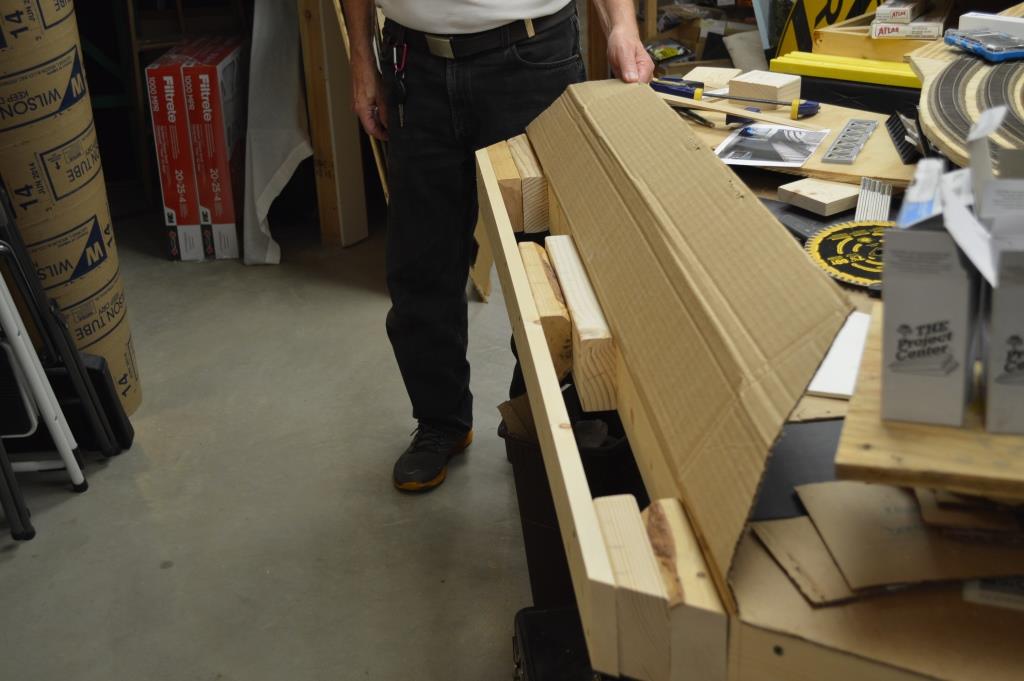
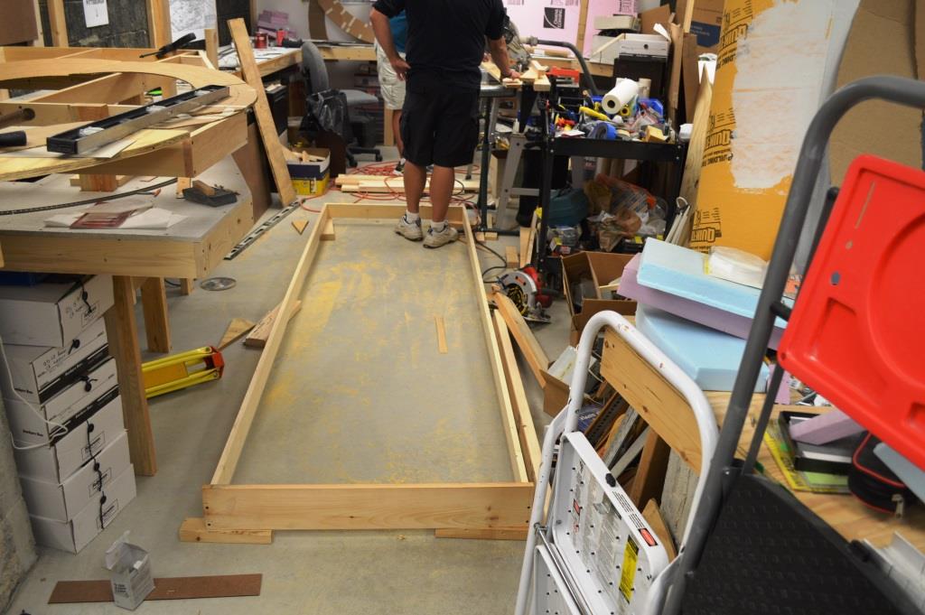
Kent and Bob attach legs to the first rectangular section of bench work, which would eventually become the eastbound staging yard. We learned that the floor was far from level, so each leg had to be a slightly different length.
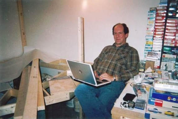
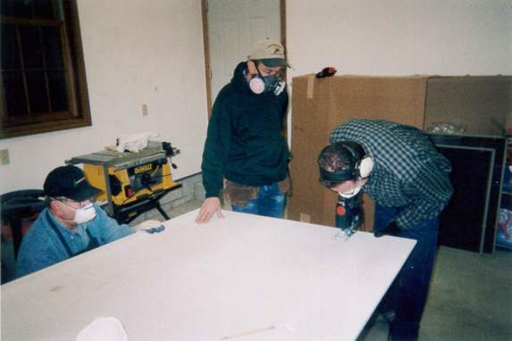
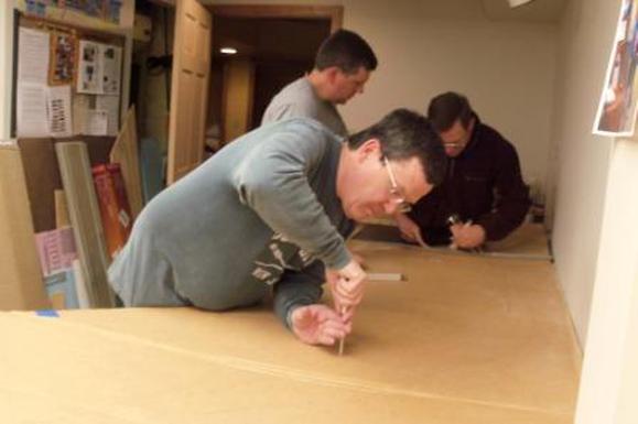
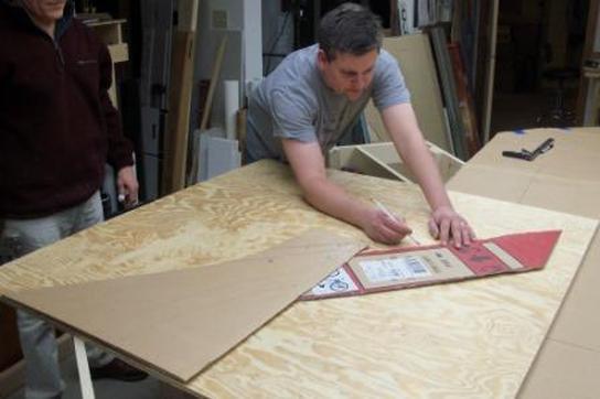
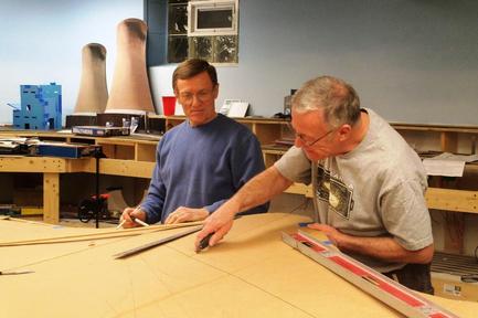
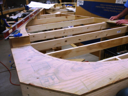
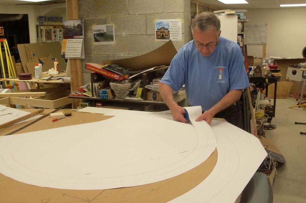
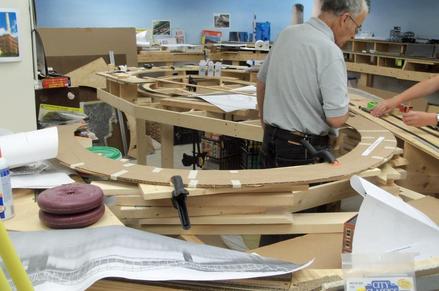
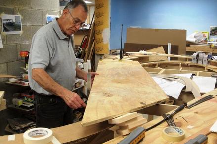
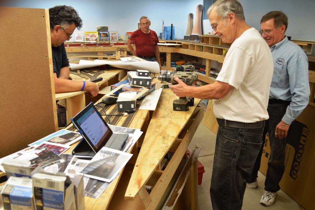
Using drafting software, Tom figured out how many semi-circles we could get out of a 4'x 8' sheet to minimize waste. A paper template was used to lay out the segments.
We used a product called Micore for the sub-roadbed on the helix. It is used in cubicle partitions and is similar to Homosote, but does not absorb moisture and therefore is dimensionally stable under varying moisture conditions.
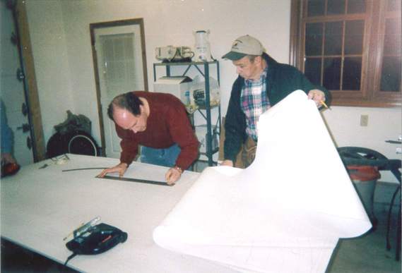
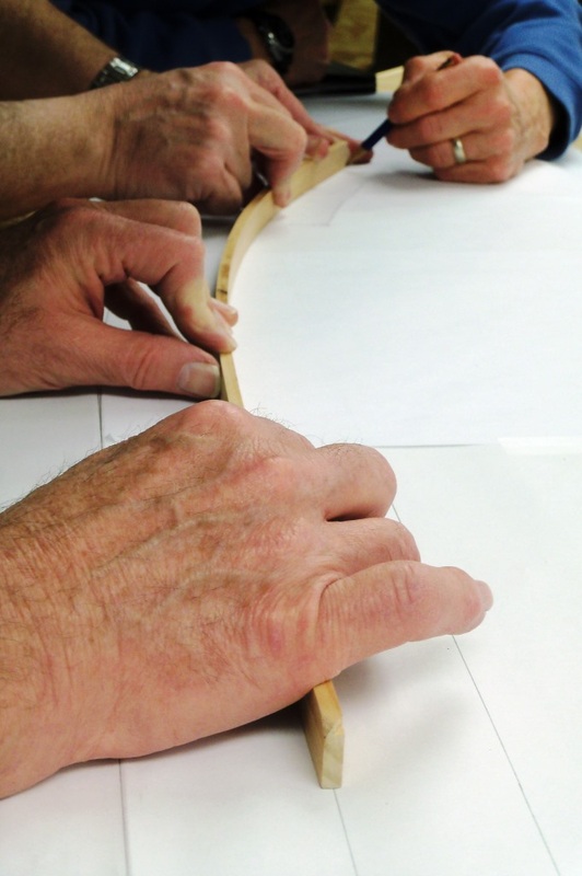
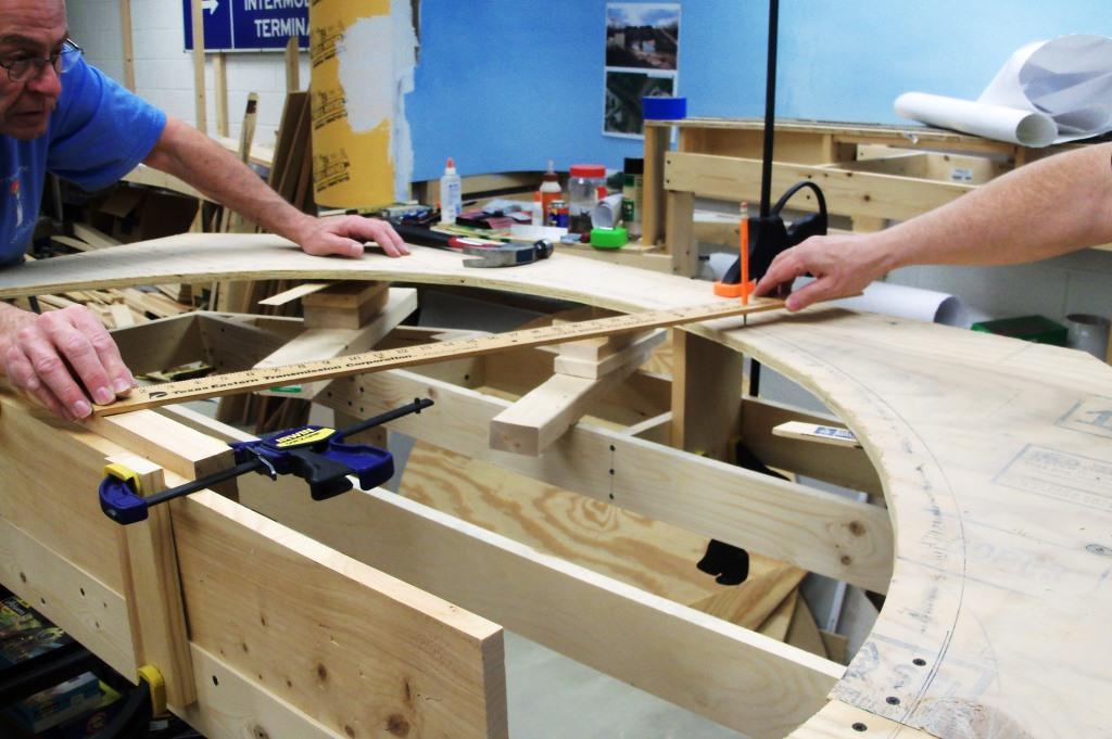
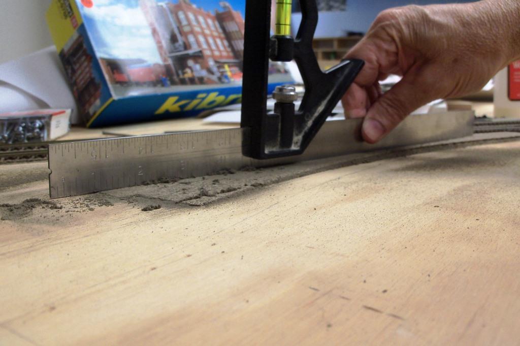
We laid out inside and outside radii for each segment using a trammel, which we made from a yardstick.
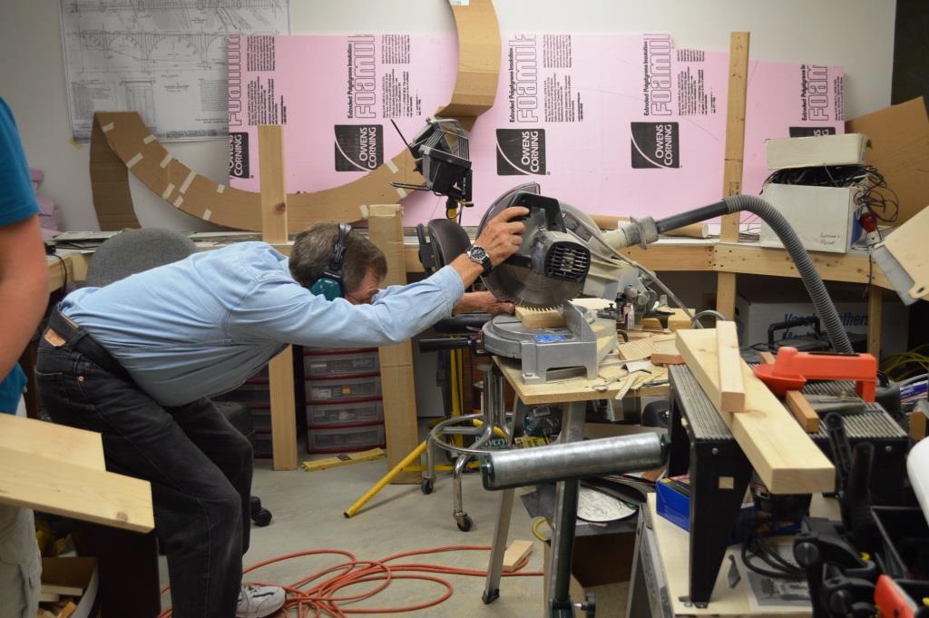
All cutting was done in the garage with breathing protection as it creates a lot of dust and particulates.
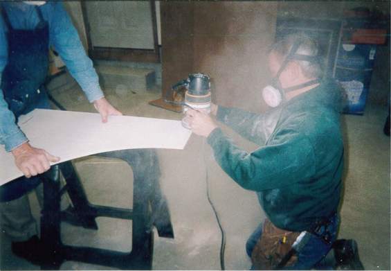
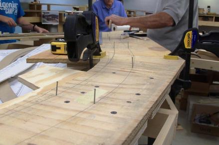
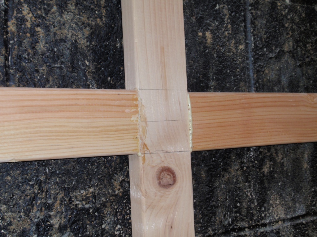
Bruce used his router to make a lap joint at both ends of each segment. This was key to reducing the rise of each revolution. This was a dusty, dirty job.
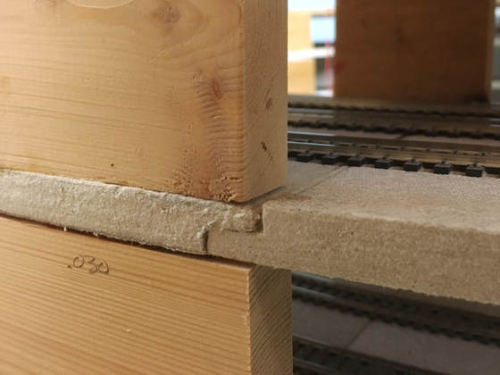
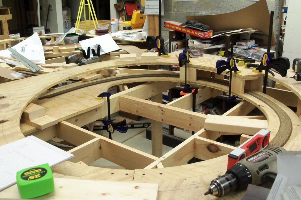
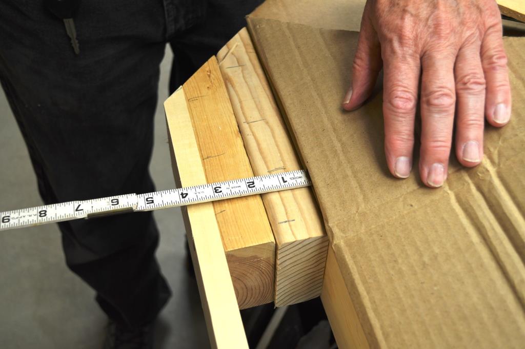
Here is a close up of a lap joint. We used the amber Gorilla Glue on these joints, clamping the two pieces together until they dried (the Gorilla Glue expands as it dries and if not clamped would push the pieces apart). The lap joints eliminated the need for "splints" under each joint and allowed us to keep the helix slope as flat as possible and minimize the rise of each revolution. We used blocks of 1' x 4" as risers, positioned on the inside and outside edge of the helix segments.
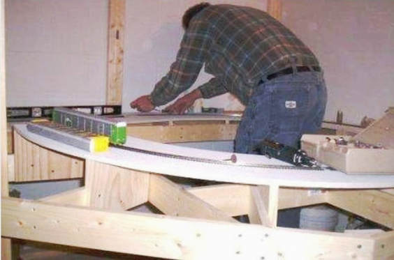
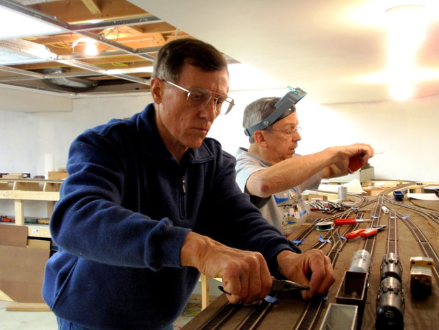
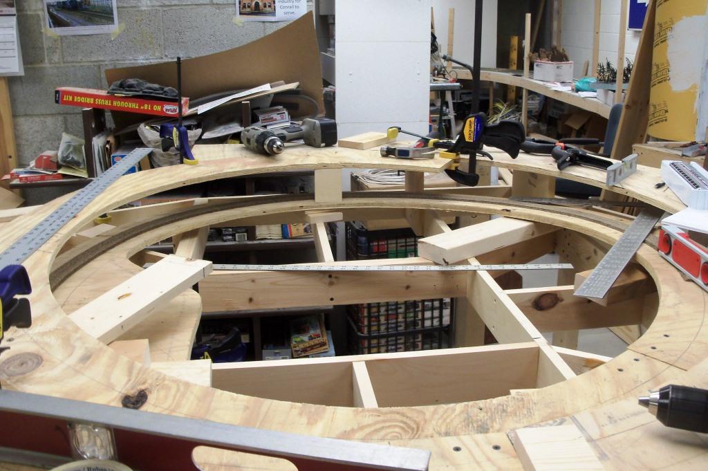
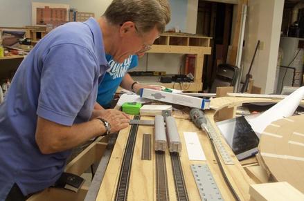
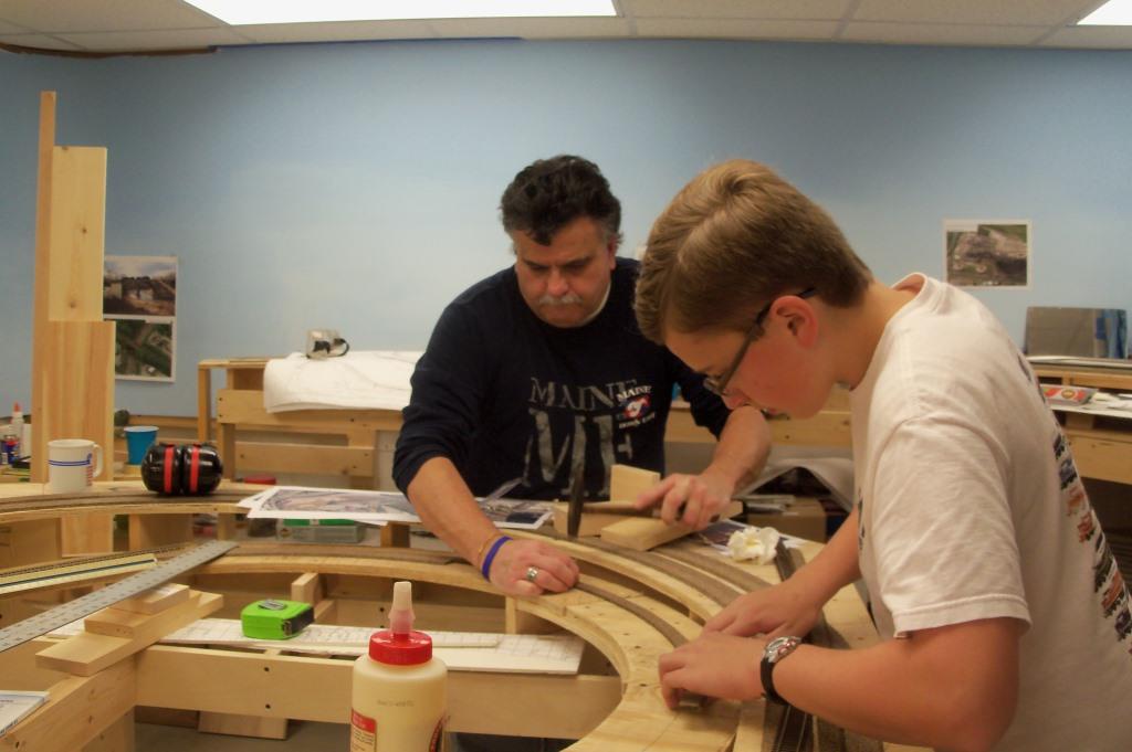
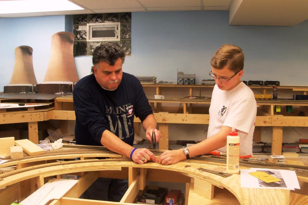
Here Tom is working on the first revolution of the helix. The elevation of the risers for the first revolution were critical, with the subsequent revolutions rising a uniform 3-1/2" per revolution. We used 89-foot auto racks to test the track work and clearances.
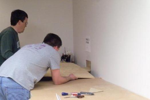
Kent and Andy size up a piece of Micore for the staging yard.
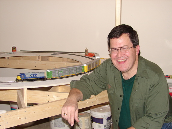
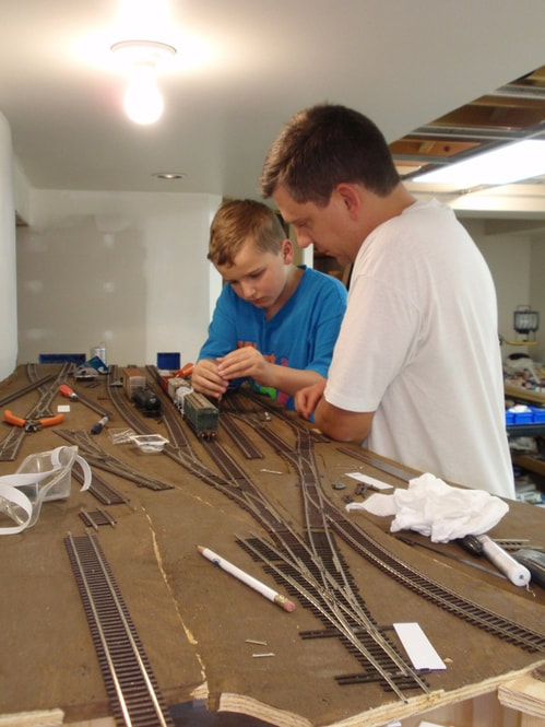
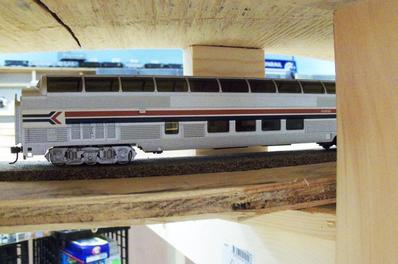
A very proud Andy poses next to the first train on the layout.
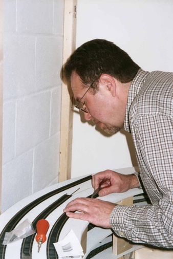
Greg is laying track on the helix. It is a few layers high at this point. The helix is three tracks wide, the innermost track is Chessie and the outer two are Conrail.
This is the completed helix. Chessie climbs an extra revolution so it comes out at a higher elevation.
2007
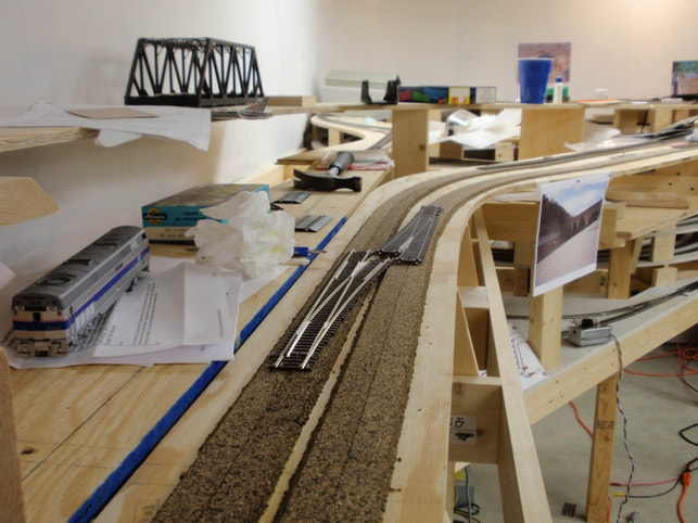
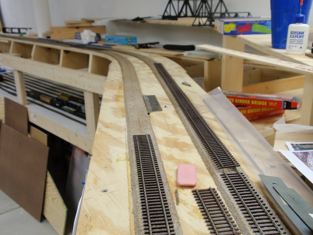
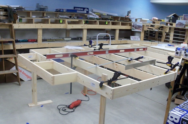
During 2007 the Chessie and Eastbound Conrail staging yards were built and the track was laid. The Eastbound Conrail staging yard is a 6 track double ended yard. The Chessie staging yard has 7 tracks and is a shorter stub ended yard.
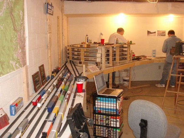
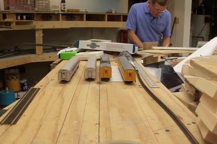
As you can see, we couldn't wait to populate the staging yard with rolling stock! On the left is the Eastbound CR staging. In the center is the helix and a reversing loop. To the right is the Chessie staging.
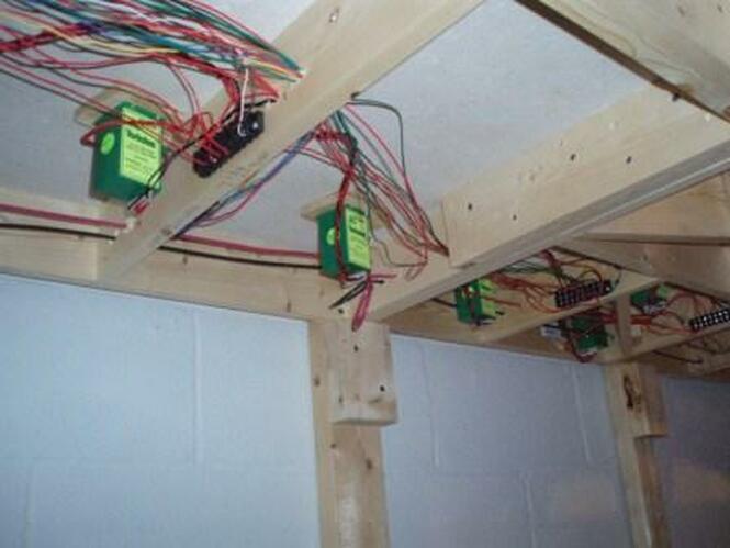
This is what is underneath the staging yard. The green and yellow boxes are switch motors.
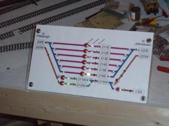
To control the switches in staging, Tom designed and built a switch panel from scratch. The panel energizes the selected track and lines the turnouts at both ends.
2008
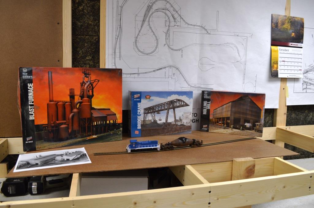
In 2008 the benchwork and track for the Chessie Johnstown yard and a few industries were completed. At first it was done on foam but we soon realized plywood would work a lot better and we relaid all the track and turnouts. Not much was done because the drop ceiling had to be put in.
Charlie and Bob are laying the track for Johnstown Yard.
Dan and Bruce are putting in the track wiring in Johnstown.
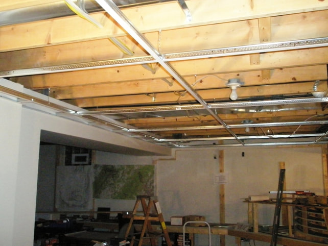
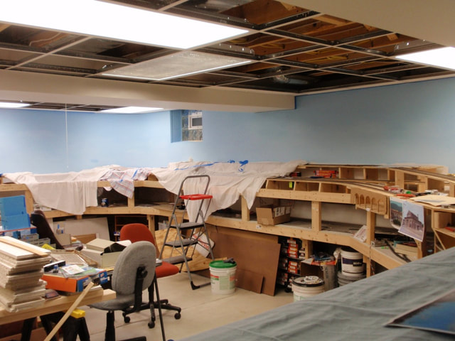
The drop ceiling.
2009
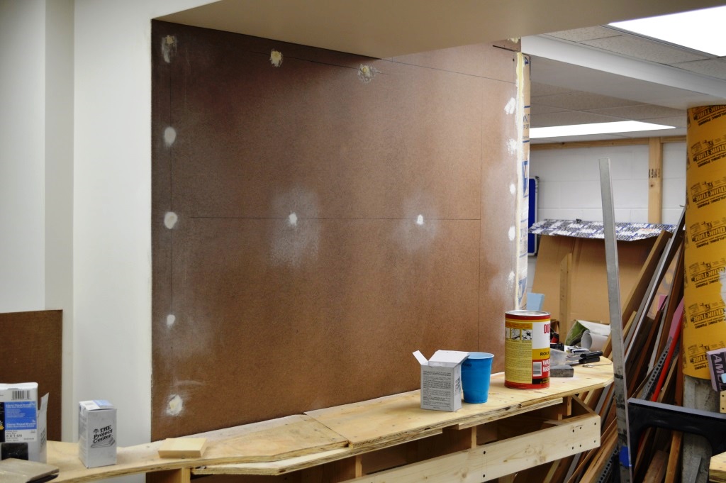
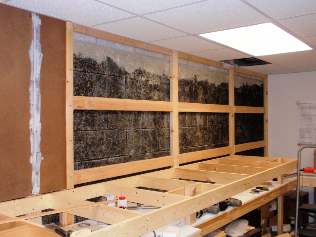
In 2009 the drop ceiling was put in for the older room. We also started planning the power plant and mine. We also put up the masonite for the backdrop. The joints between sheets of masonite were taped and mudded just like drywall joints.
2010
In 2010 Andy had to finish the new room by putting waterproofing sealer on the foundation walls, and installing drywall at the far end against the stairs. But we did manage to extend the mainline to Latrobe and paint the backdrop.
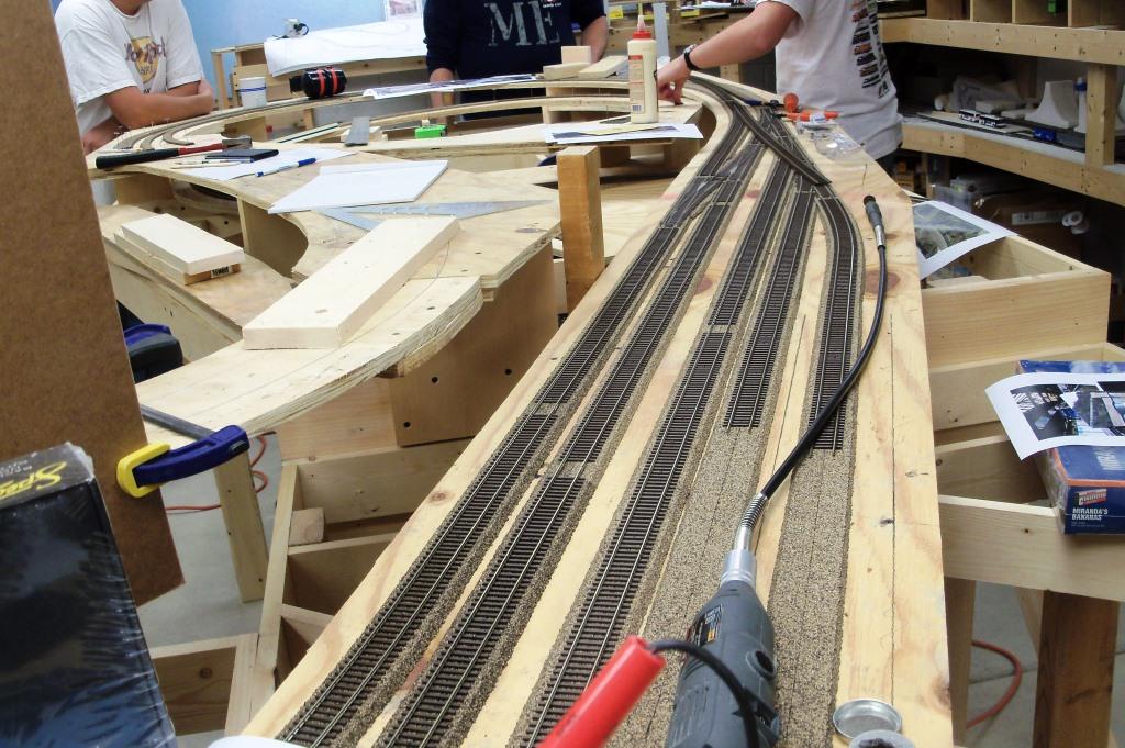
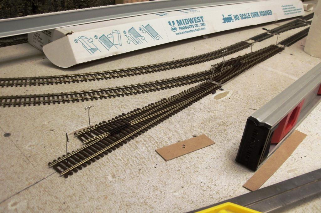
Here the cork is laid for the mainline. To the left is where the interchange tracks will go. The No. 8 switches show where the crossover will be.
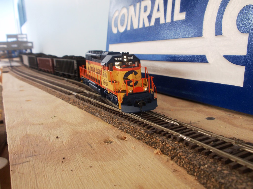
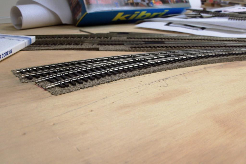
The mainline is starting to take shape. Atlas Code 83 flex-track and turnouts were used on visible parts of the layout; Code 100 was used in staging and for the helix. This photo shows the tracks at Johnstown Station, where there will be a platform between the two main line tracks.
Here is the completed backdrop. We might add clouds later.
2011
During 2011 the Westbound Conrail staging yard was built. The track was put in for Cambria Iron Works in Johnstown as well. Also the cooling towers were made.
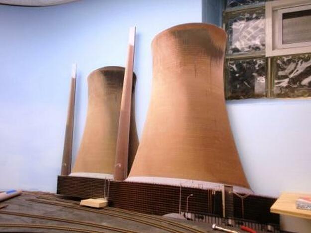
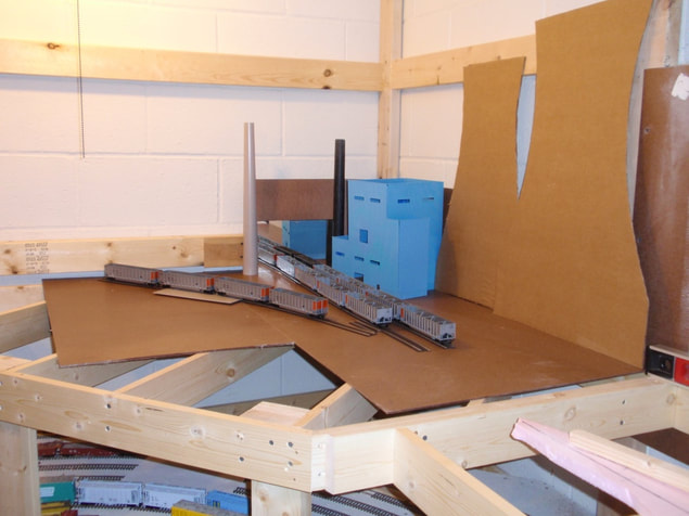
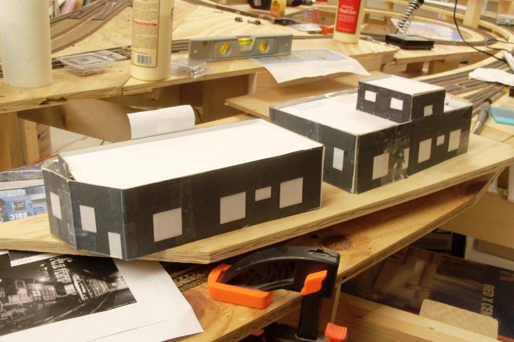
The two cooling towers are actually the same photo in different sizes mounted on foamcore. Andy took the photo at the same power plant we are modeling, the Conemaugh Generating Station in New Florence, PA. The smoke stacks will be cut off. Thanks to Alan Fleissner for plotting the photos.
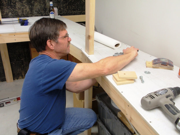
Gary is putting on mounting blocks for the switch motors in the westbound staging yard. The plywood mounting bocks were affixed to the underside of the Micore with Gorilla Glue and they give the switch motor mounting screws something solid to thread into.
This is a part of the benchwork for the staging yard. On the lower level, Micore is used instead of plywood because it doesn't need to be as strong (Micore is similar to Homosote).
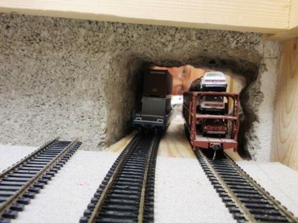
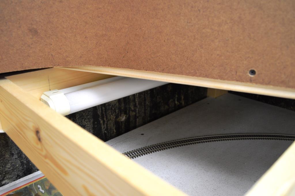
To get into the newer room the bottom level goes though the block wall in a tunnel that Andy jack hammered out. This picture shows how tight the clearance is with taller cars.
2012
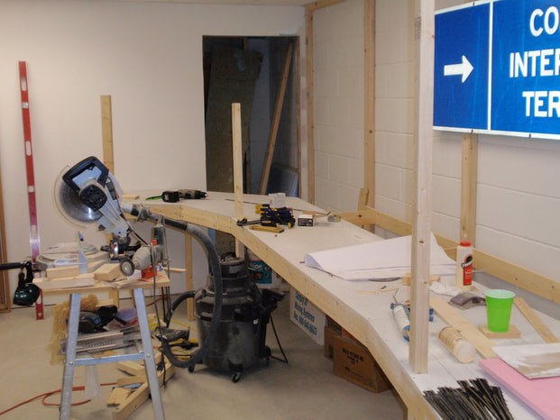
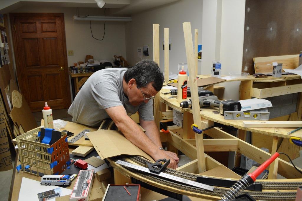
During 2012 we began to work East from Island Avenue.
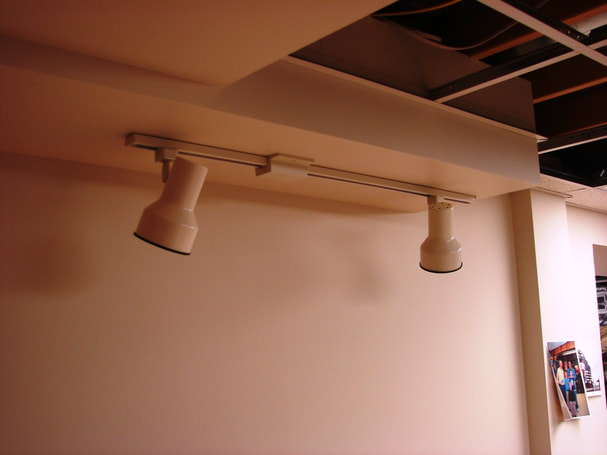
Track lighting has been added above Island Avenue Yard. Much easier now before the yard is in place!
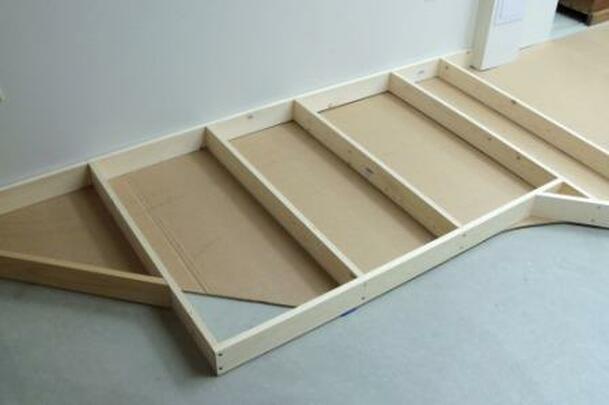
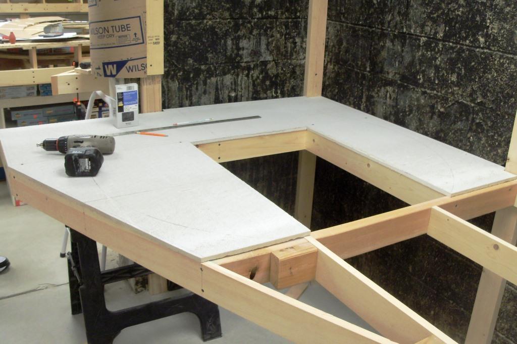
Here is the first piece of benchwork for Island Avenue yard. Underneath you can see the cardboard that we layed out the track on originally.
10/5/2012
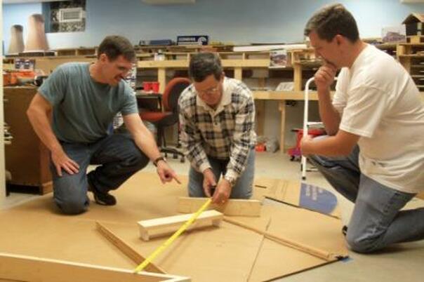
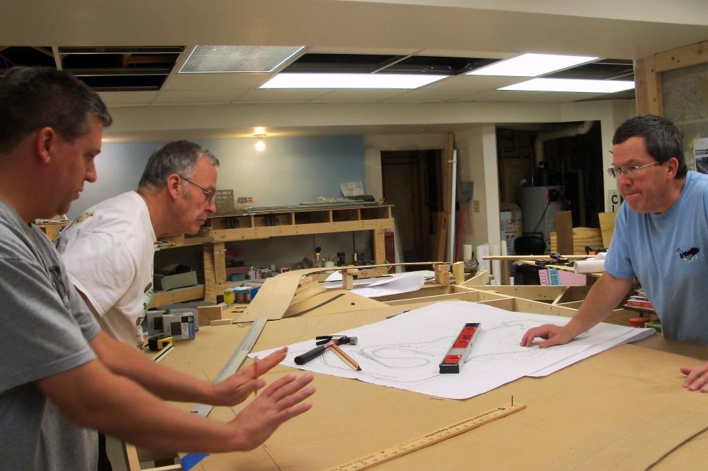
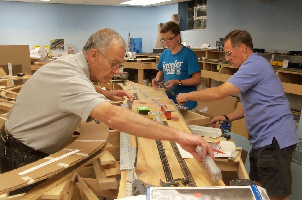
Gary, Andy, and Bob discussing ideas on where the Fort Wayne Bridge should go.
Gary and Andy are trying to decide about where the scenery block should go coming into Pittsburgh.
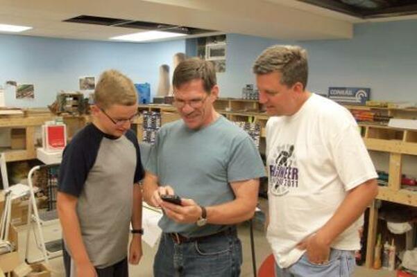
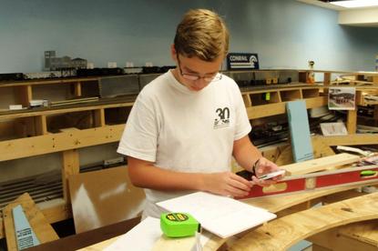
As the evening wound down, the discussion drifted to Schnabel cars. Here Gary looks up the word on his smart phone. For future reference, the word "Schnabel" is from the German word Tragschnabelwagen, meaning "carrying-beak-wagon." No worse that fahrvergnugen I suppose...
10/26/2012
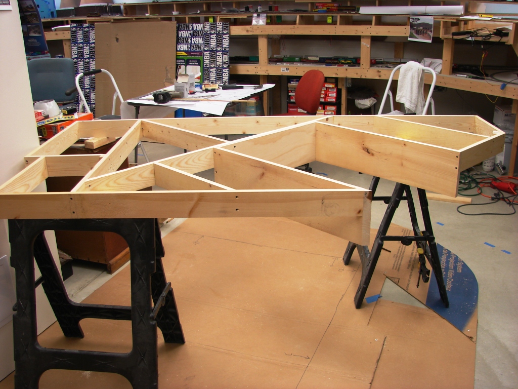
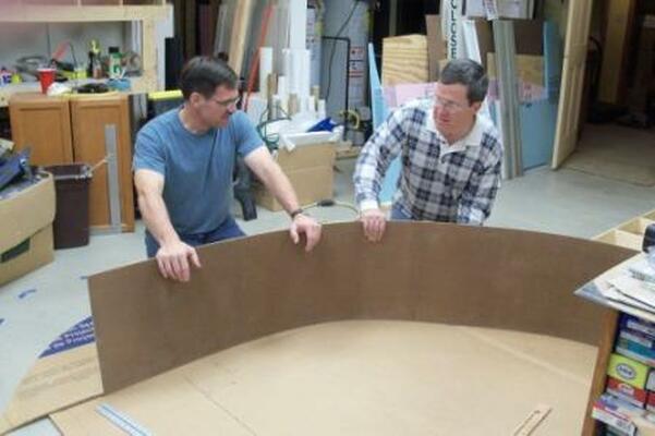
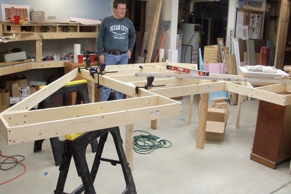
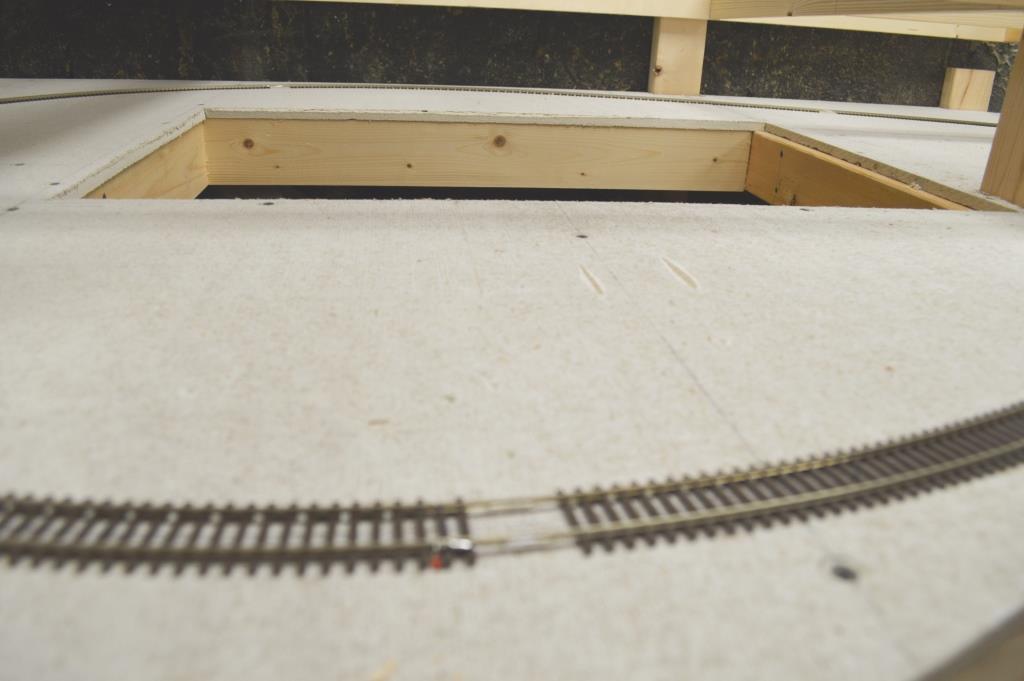
The next section of bench work was completed on 10/26/12. The "drop" section will be the Allegheny River with the Fort Wayne Bridge against the backdrop.
|
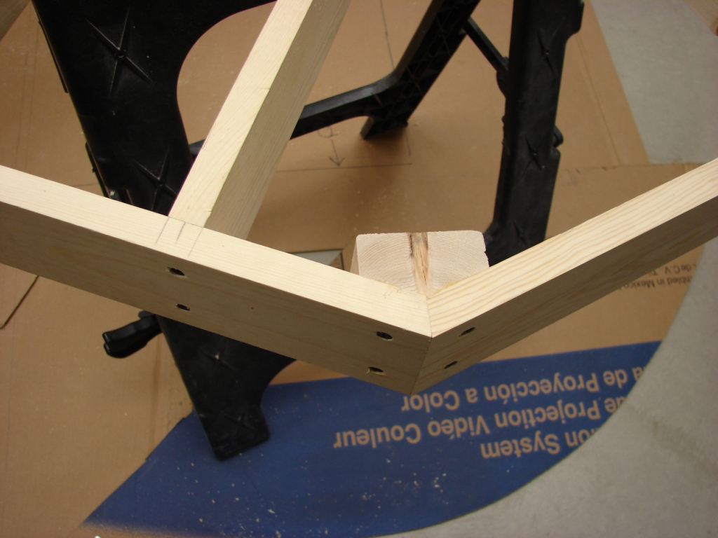
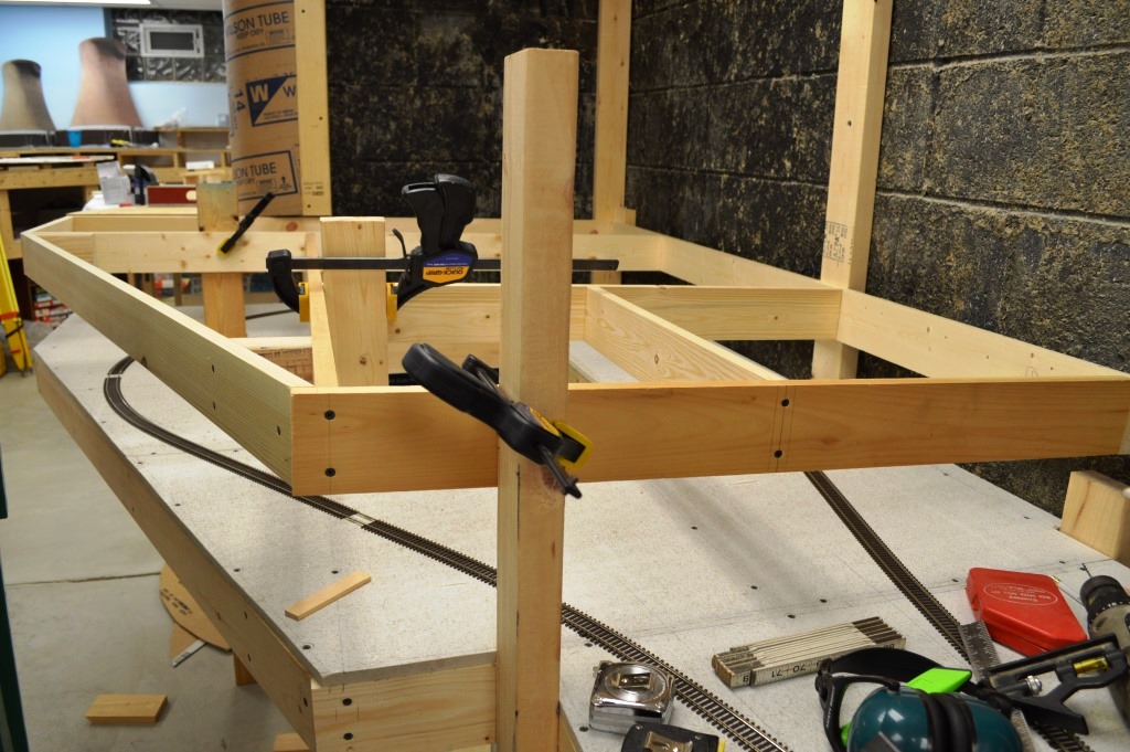
Look at that reinforced joint! Bruce would be proud.
|
11/2/2012
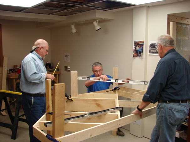
Howard, Jerry, and our guest Mike Rabbit level a piece of benchwork in the area where Pittsburgh will be, prior to attaching legs.

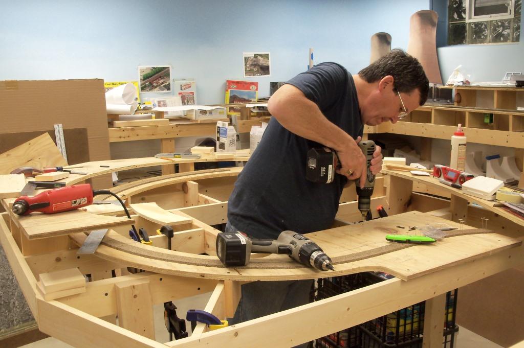
Mike screws in a leg while Howard and Jerry hold things in place.
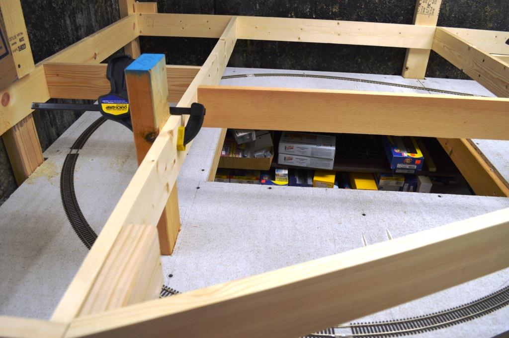
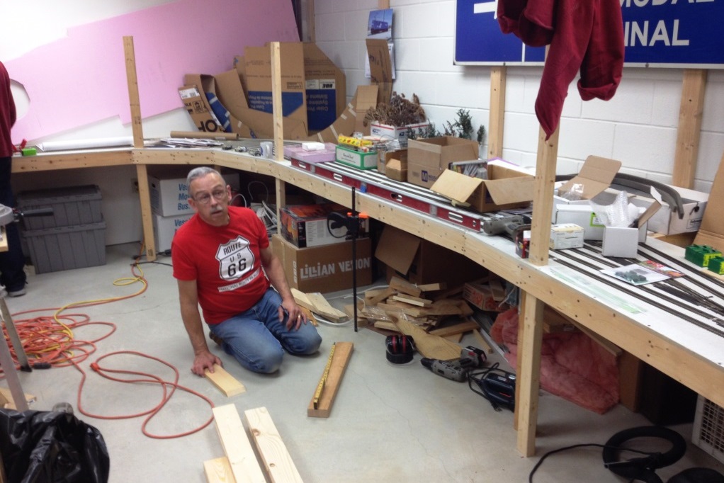
As we build more benchwork, a huge shelf that stores the majority of our locomotives and rolling stock had to be moved under the newly built benchwork. Luckily we had five guys come that night and it took all of us to move it!
Here the shelf sits in its new place. It must be 8 feet long and weighs a ton! Hopefully we will never need to move it again!
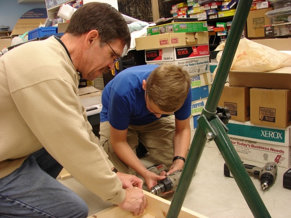
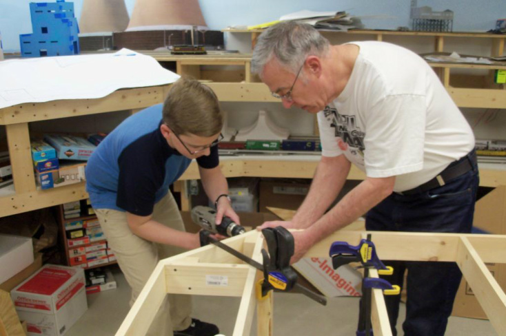
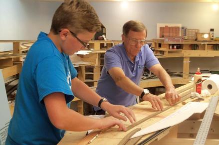
Charlie is beginning to learn some carpentry skills and is screwing together the next piece of benchwork as Gary supervises.
At the end of the evening Andy looks and admires all the work he and his crew got done. The PML is on a roll!
2013
1/4/2013
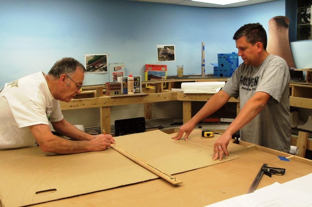
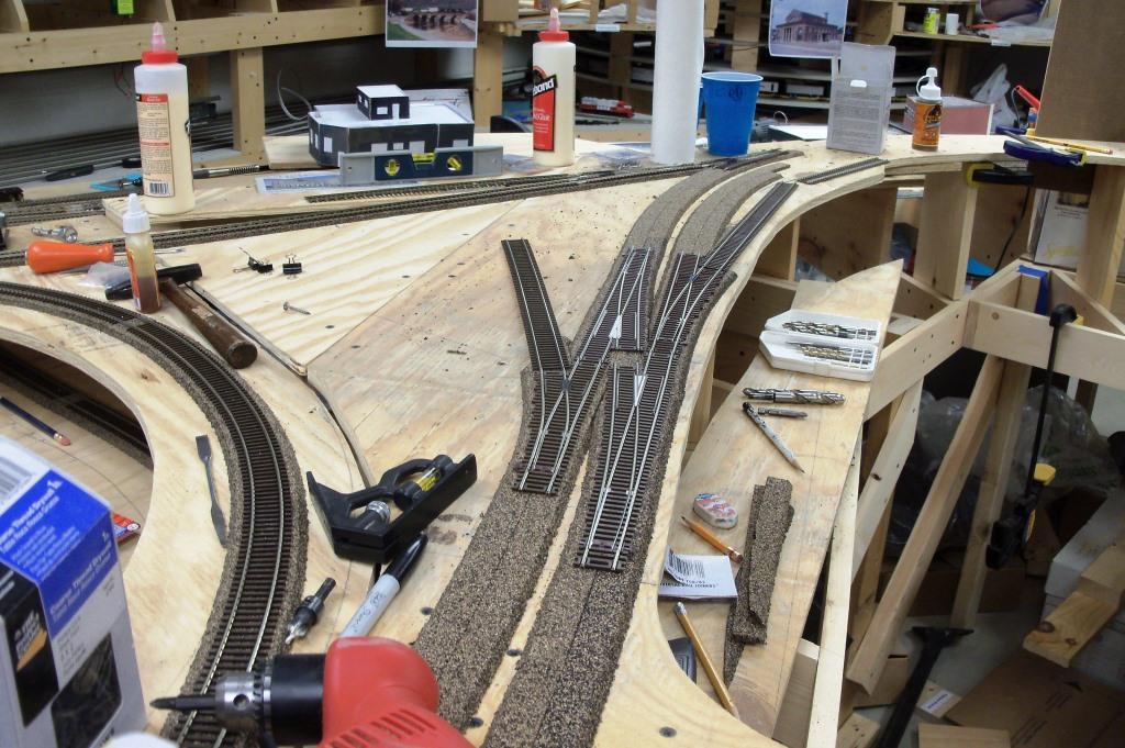
Andy works on transferring the track plan for Island Avenue from the cardboard template to the plywood.
Andy, Dan, and Bob discuss what the best way would be to bridge the gap between the two rooms in the tunnel.
Before cutting the plywood we made a cardboard template of the segment that will extend through the tunnel.
Success! It fits into the tunnel.
2/1/2013
Gary, Jerry, and Dan work on the next piece of benchwork as Howard looks on.
Howard screws a joint as Dan holds the wood.
This big piece of benchwork is almost done as Dan assembles the last section.
One more piece and the benchwork in this room of the layout will be complete!
While the other guys worked on the benchwork Mike and Charlie drew the track plan on the plywood for Island Avenue.
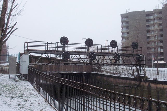
On the next day we were in the area and dropped by West Park. The old postition light signals are still in place. We will try to replicate this scene on the West end of the layout where the tracks go through a tunnel to staging.
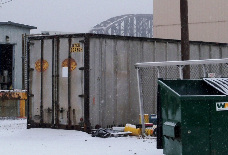
At Island Avenue Yard we also saw and old container now used for storage and still in NYC paint!
3/1/2013
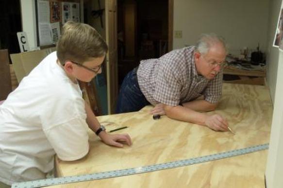
We had a light work crew Friday - Jerry, Charlie & Andy, but what we accomplished was done well and sets us up for the next work session. Here Charlie and Jerry add a diagonal brace to the corner of the benchwork. They also leveled the last two sections of benchwork, and cut and attached permanent legs. (This area will be Shadyside/East Liberty on the completed layout.) Charlie reports that Jerry is a great teacher of carpentry skills.
Here is their finished work. Note the reinforced corners for strength. Not only does it look great, but the bracing really stiffened up the benchwork. The blue masking tape on the floor was our dimensional guide for the benchwork so we maintained 36-inch aisles.
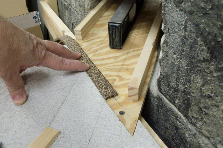
Meanwhile, Andy made adjustments to the plywoodf sub-grade that will carry the mainline through the foundation wall from staging to Island Avenue Yard. 3/8" was trimmed from the top of the benchwork, which allowed for a drop off to exactly match the cork roadbed thickness. Howard suggested this so the track can be spiked to the cork rather than plywood, which will be much easier in the "tunnel." Note the siderails which were added last session; they took the warp out of the plywood but will also will help protect rolling stock in the event of a derailment.
A 3-foot level with a small piece of 3/4" thick lumber under the downhill end exactly met the desired 2% grade, allowing a riser to be cut and installed.
While the riser was attached with just one screw, side-to-side level was checked before the second screw anchored the riser to the benchwork.
11/22/2013
We pretty much took the summer off to chase and photograph real trains and Heritage locomotives, but now the lawnmower is put to bed for the winter and it is dark at 5 pm, so it's time to get back to layout construction. Jerry and Bob were available on short notice and came over Friday night to help.
Charlie thrives on laying track and he does a very nice job at it! Last session he and Bob made the transition from Code 100 in staging to Code 83 and got the track laid through the wall. This session he picked up where they left off and installed some flex track, then the crossover in West Park and one of the turnouts to the AVR interchange track. The finished job, at right, looks great.
|
|
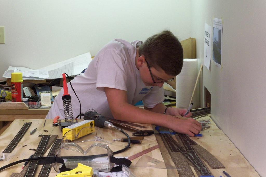
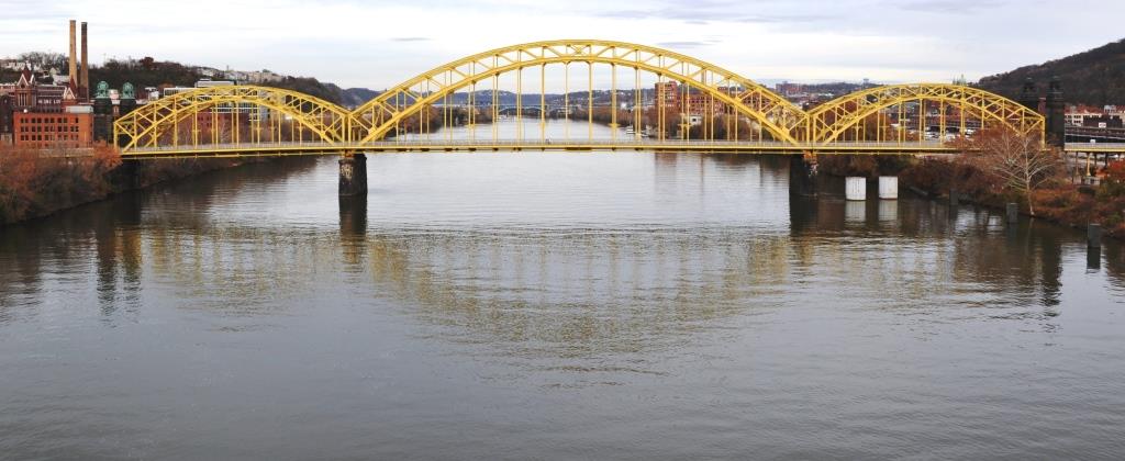
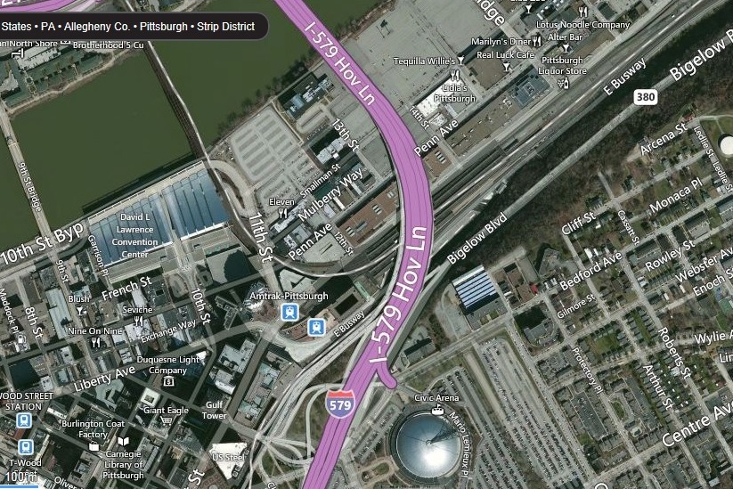
Around the corner, it was time to finalize the alignment of the Fort Wayne Bridge, which in the prototype carries the main line across the Allegheny River. We wanted to include the 16th Street Bridge (recently renamed for author and Pittsburgh native David McCullough) in the background as this would have been the next bridge upstream in our time era. It is possible to photograph this bridge from Interstate 579 on the Veteran's Memorial Bridge, but our camera does not have a wide angle lens. Alas, my brother John was in town last weekend and he is a skilled photographer with a nice collection of lenses. He readily agreed to try and get the shot and the end result is terrific (see below). We plan to have this professionally printed and adhered to foamcore board as we did with the cooling towers for Conemaugh Generating Station. The key will be to get the print to the right size to match the river banks.
Jerry checks level between temporary wood bridge abutments, which will be a starting point to determine our final grade.
|
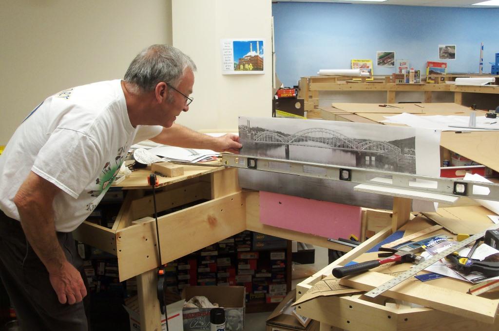
Jerry, Bob and Andy couldn't resist the opportunity for a photo behind the temporary bridge (a three foot level for now) with a test plot of the 16th Street Bridge for a backdrop. This has some potential...
|
It quickly became obvious that we needed to determine the location where the next tangent track segment would be so the sharp curve at the Pittsburgh Station could be laid out.
|
This pushed us out the the end of the peninsula to lay out the curves using our trusty trammel fashioned from a wooden yardstick. We are dropping the radii of these curves from 32"/30" down to 30"/28" so that we can include a section of the Port Authority's East Busway between Wilkinsburg and Pittsburgh. We will compensate for the tighter turn by backing off on the 2% grade a bit.
|
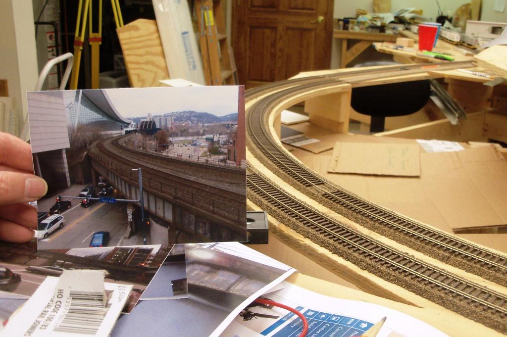
The main line alignment starts to take shape as we fit a cardboard template of the sharp bend coming off the Fort Wayne Bridge and into the Pittsburgh Station. This will be the tightest curve on the mainline, just as it is on the prototype (see at right).
|
|
January - February 2014
Although it has been quite a while since we posted a progress report, we have had a half dozen work sessions this winter and are moving forward. Here are some recent photos.
After deciding on the alignment and making a paper template with the track centerlines marked, it was time to cut the sub-roadbed from plywood. We had been given some weathered 5/8" material left over from a construction site. The price was right and the additional thickness will be helpful.
Elevations are also critical at the risers in order to achieve the desired grade. Since the drop grid ceiling was set with a rotating laser level, we have used that as a reference. In reality, the ceiling has proven to be much more level than the floor. Here we check the riser elevation at the downtown Pittsburgh end of the Ft. Wayne Bridge. Two sections of plywood were spliced together to create the curve just east of the bridge and the straight station tracks.
I'm not saying this is for everyone, but if you have a tripod and a level (I do), that is another way to check elevations to achieve a desired grade. We backed off to 1.5% through the sharp curve adjacent to the bridge, but then ramped up to 2% on the straightaway.
|
Next it was time to transition to the straight tracks through Pennsylvania Station in Pittsburgh. We took our time and laid out an easement (spiral) to exact dimensions on the outer track, However, rather than go through the same process on the inner track, as a time saver we used a "bent stick" as a template to draw the track centerline and it worked very well.
Here is a close-up showing the "bent stick" method of drawing a spiral. A piece of 3/8" lattice was used for the stick. One end of the stick is aligned with the straight track centerline, while the other end is fitted to the constant radius curve, which is offset from the straight track centerline. It takes several hands, so this is not a one man project, but the results were very good.
Nearly always there is some warp to the plywood, so we set the riser at the far end of the piece of sub-roadbed, and will then clamp a straight piece of wood or a 6-foot level to the plywood to achieve a uniform grade. The track alignment is not perpendicular to the benchwork framing, so the risers need to be adjusted to compensate for the grade. Our actual measured grade after setting the far riser was 1.92%.
|
3/7/2014
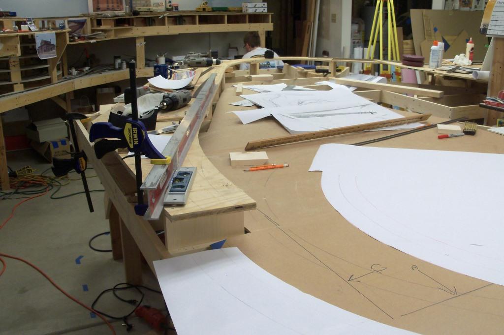
Planning ahead to the next segment, Dan and Jerry remove the section of cardboard we had used as a planning template that has now been constructed out of plywood. The remainder of the cardboard sheet will be used to lay out track and make a cutting template through Shadyside, East Liberty and Wilkinsburg.
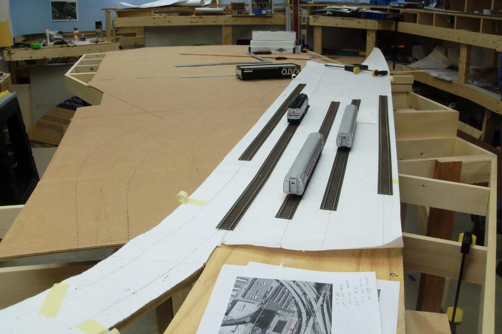
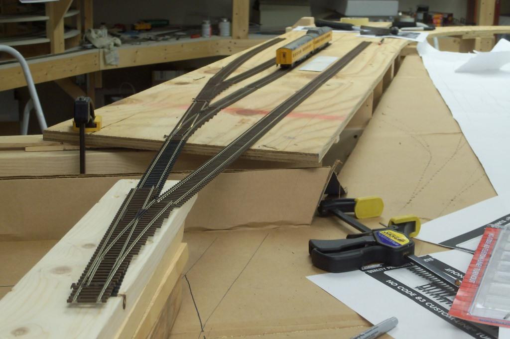
Next we laid out our concept plan for the passenger station trackage. The two tracks on the left are mainline through tracks, while the three on the right are stub-end station tracks with platforms and a train shed. An aerial photo of the station and train shed from Google Maps lies in the foreground as a good reference.
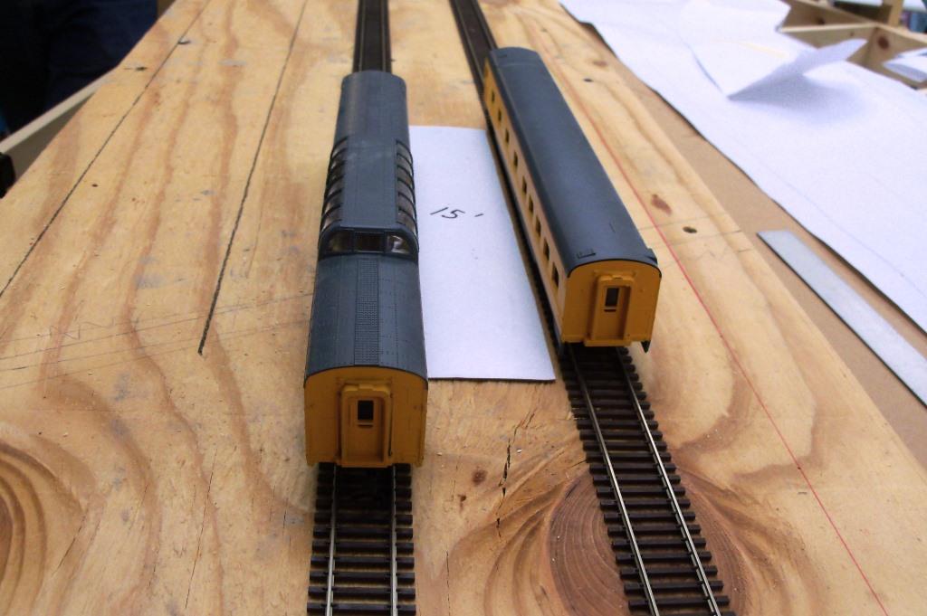
We decided that 15 scale feet was sufficient for passengers and baggage handling carts. Pardon the foreign UP passenger equipment - they don't have boxes and it was easier than getting the Amtrak equipment out of its boxes again!
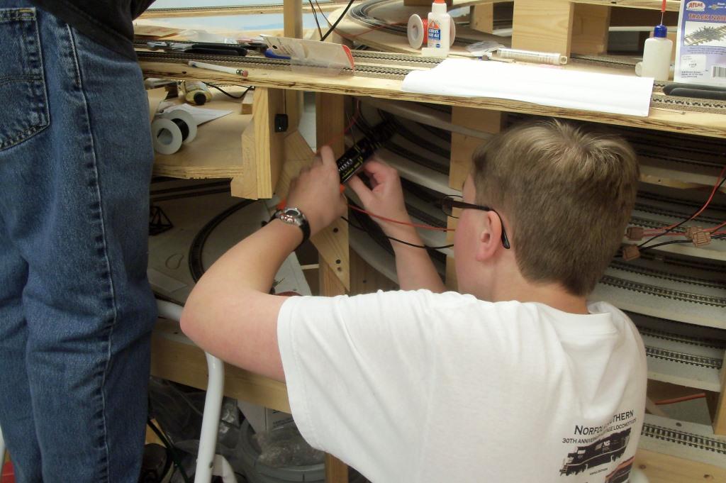
Meanwhile, Bob and Charlie work on completing wiring in the Johnstown area. Charlie drops feeder wires to the bus wire, which was extended last session.
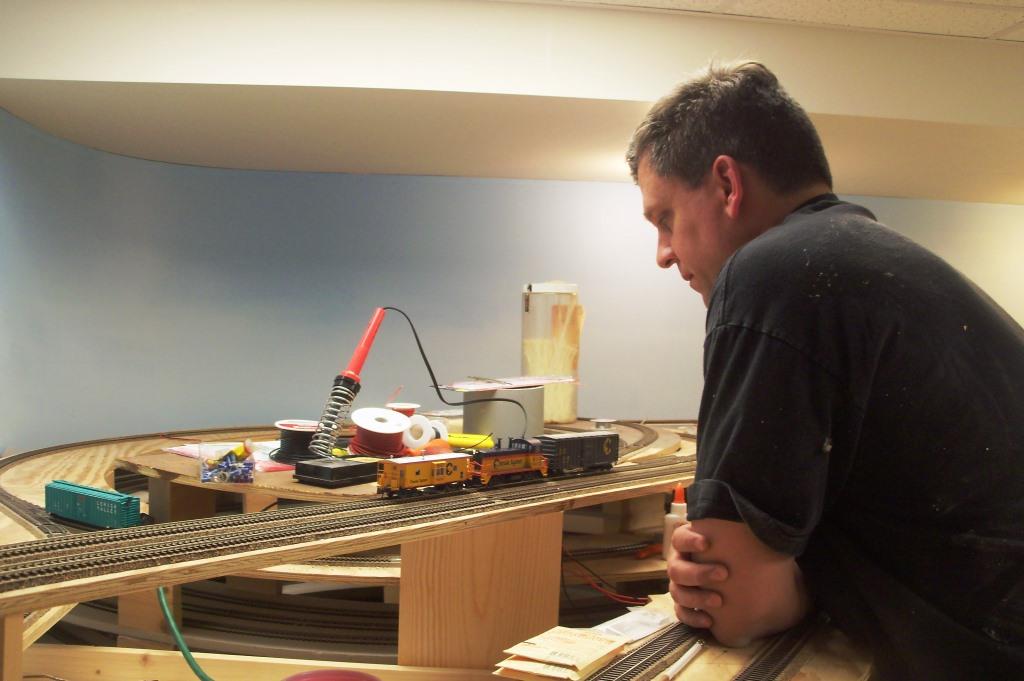
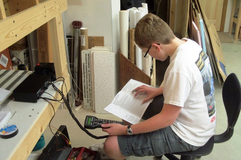
At the end of the evening, the bus wire was energized and a loco, box car and caboose made the first run to the coal mine! Bob watches for any track problems as the train passes by. We finally made the decision and purchased a radio (wireless) DCC system from NCE. We now need to purchase three reversing loop circuits to complete wiring through to Latrobe.
|
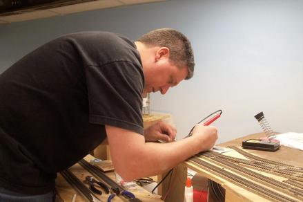
After taping our paper template (that had been used earlier to cut the plywood) in place, Dan uses a punch to transfer the track centerlines to the plywood. With the rough and weathered surface on the plywood, we had to emphasize the holes with a Sharpie so we could see them on the plywood.
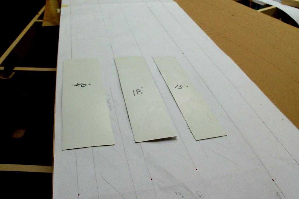
Using scaled cardboard templates, we test fit platform widths of 15, 18 and 20 scale feet.
Unfortunately, it appears that the spacing between adjacent tracks will also be dictated by the minimum spacing between turnouts (we are using Atlas #6 in the passenger station). We will transition into the next curve, a full 180-degree turn, with a right-hand turnout in order to maximize the length of the station tracks.
Bob works on removing a bad turnout coming off the Chessie tracks into Cambria Iron Works. This is the second bad turnout we've discovered in the past two sessions. The last time we found a turnout that was shorting internally, and this time the defective turnout was not conducting power through the connection to the moving rails. Fortunately, both were relatively easy to replace. We will be checking all future turnouts before soldering in place!
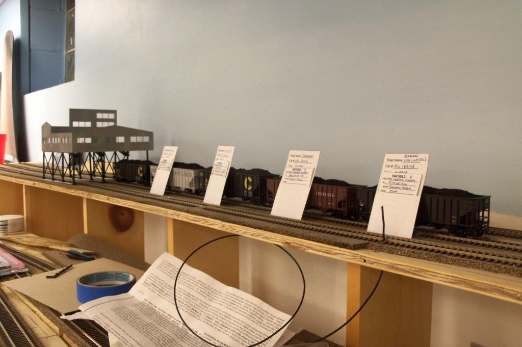
Within minutes, Bob unpacked a fleet of his cars that he has tuned up and readied for operation. He set them out at future industries, complete with their car cards. Is it obvious that Bob is anxious for an operating session!
|
4/4/2014
With the sub-roadbed in place through the Pittsburgh Station and Strip District, it is time to move east to Shadyside and East Liberty. The first step was to transfer the track centerlines we've already drawn on cardboard onto paper.
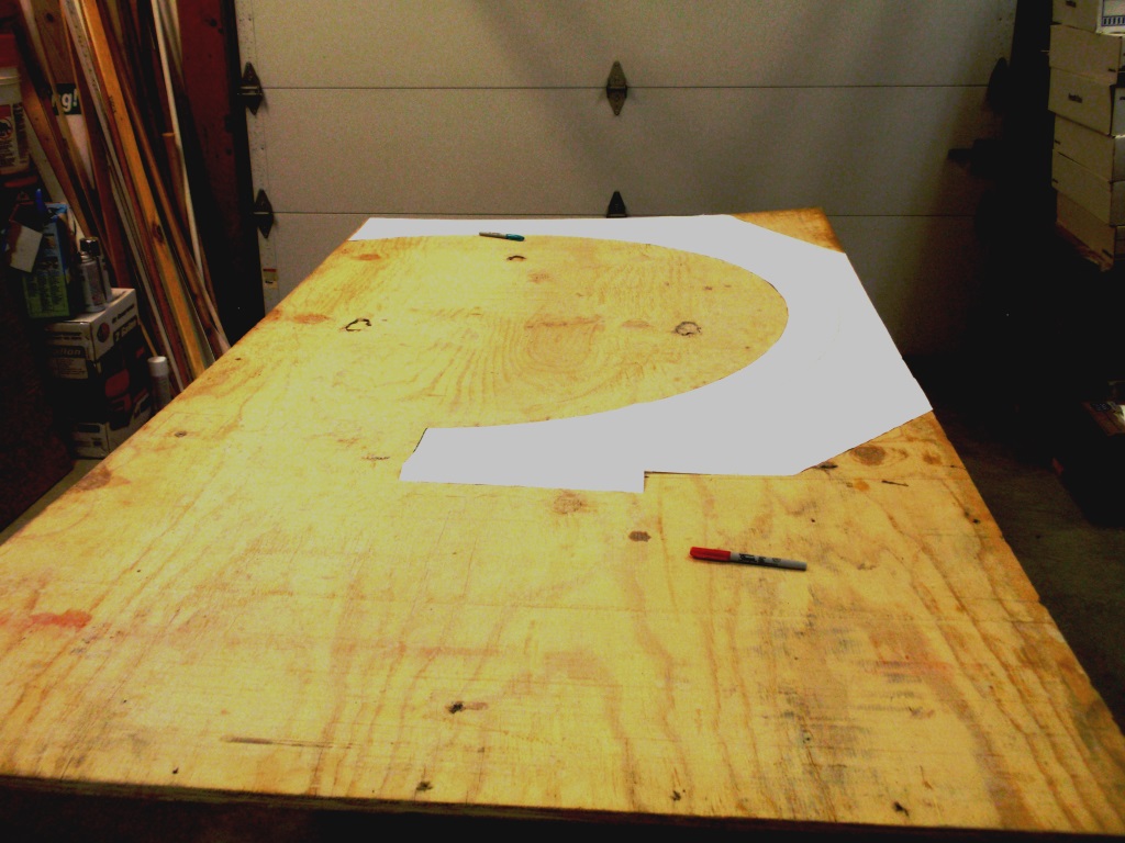
The pattern (or template) was traced onto the plywood. We carefully placed it so we'll be able to cut the reverse curve from the same sheet of wood.
We checked the fit before setting some temporary risers to achieve the desired grade.
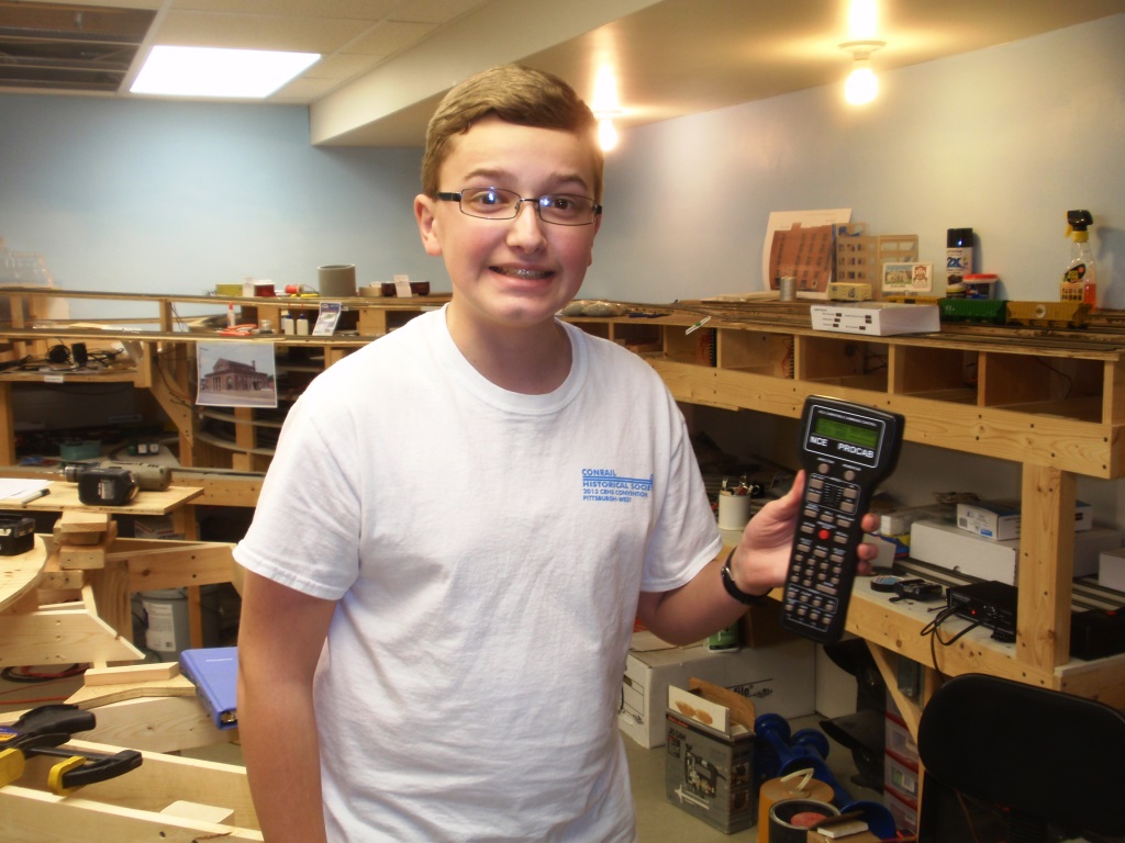
Meanwhile, Charlie has unpacked the new NCE DCC system and set to work hooking it up.
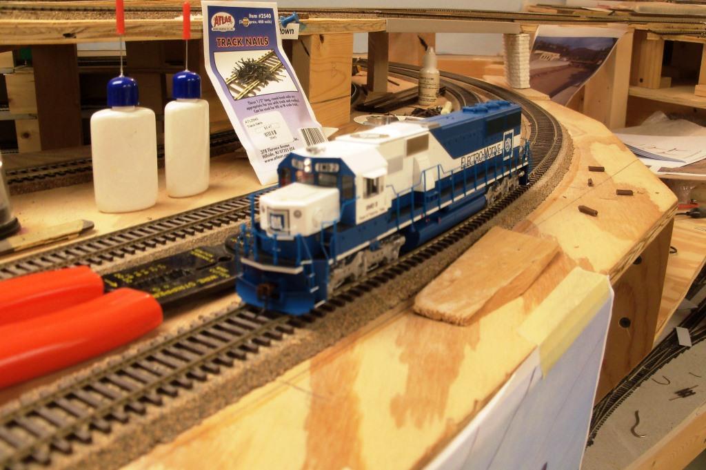
And they're off! Charlie chose an EMD demonstrator SD60 (the newest engine on the railroad) to take the maiden voyage with the new DCC system.
Here Charlie tries out the smaller Cab06r throttle which has both a rotating knob and a digital readout. Everything you could want in a throttle and then some.
|
We drew a width of 6 inches for the mainline. Here Jerry cuts out the paper to make a template for cutting the plywood. We decided to extend the plywood out to the benchwork perimeter to help support the fascia board. We will use foam sheets to build up a hillside in between to help protect the track.
...and voila, Charlie and Jerry fit the cut plywood into place.
With our cardboard template displaced, we realized that we needed to re-establish the center of the circle to help us draw track centerline arcs on the plywood. We constructed a temporary benchmark to anchor the trusty trammel. This centerpoint will also serve as the center of the helix to take the AVR track down a revolution to the Strip District.
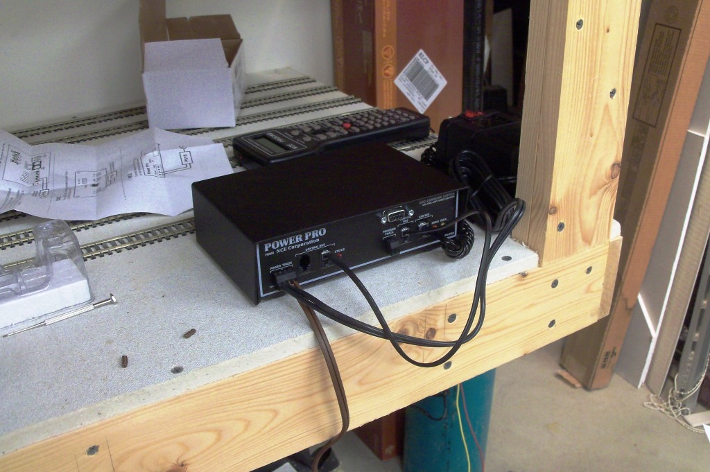
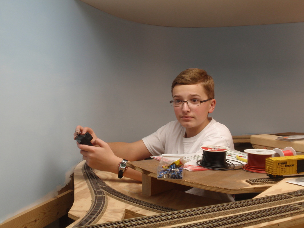
We chose the NCE Power Pro system which features wireless radio throttles. This is not its permanent location, but is a good place for testing it out.
Look Ma, no wires!
And finally, he brought a train of loaded hoppers down fom the mine to Johnstown. This is a Broadway Limited Imports SD40-2 with operating ditch lights in Chessie paint. Nice!
|
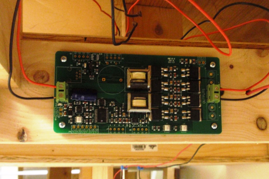
Here is a close-up of the auto-reverser circuit board we installed for the wye at Johnstown. It is a PSX-AR retailing at Tony's Train Exchange for $53.95. It includes a lot of bells & whistles we really don't need, but hook-up sure was easy - just 4 wires and screw terminals at that.
After installing the reversing circuit, a Chessie SD40-2 made the first run over the Johnstown wye.
September 2014
After taking the summer off, we are getting busy working on the layout again. Here are a few recent photos.
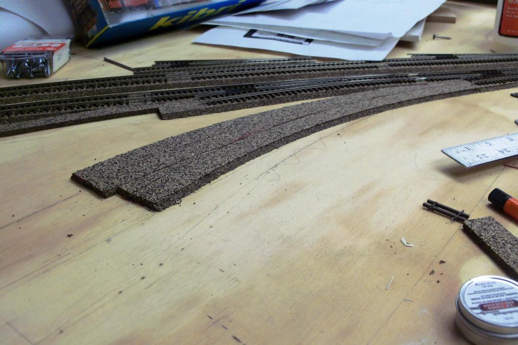
It was time to lay track into the intermodal yard, starting with a Walthers curved turnout. However, we had built in a slight upgrade coming into the yard and that looked like it would cause problems for the [rather expensive] turnout.
|
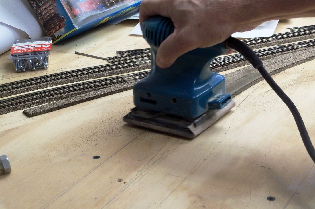
This electric sander was just the ticket to even out the cork roadbed and eliminate, or at least minimize, the vertical curve.
|
Frequent checks with a straightedge ensured that we did not go too deep.
|
We tapered the cork right down to nothing, which will accommodate sheet styrene to simulate concrete in the yard, but also eliminated the vertical curve.
|
Using 5/8" plywood, we also cut sub-roadbed for the AVR helix (Helix #2) down 6 inches to the Strip District. The curve radius will be 24-inches, the largest we could fit inside the main line. We also modified the benchwork to allow center access to fix any future derailments on the helix.
|
We were able to get the 1-1/2 revolutions in two pieces of wood, which we connected with a "splint." Here we use temporary blocks and clamps to work out the needed grade, about 2.5%.
|
Charlie calculates the riser heights needed at the spoke positions on the helix.
|
While we won't be running double-stacks or auto racks down this helix, our objective is to maintain sufficient clearance so that passenger trains can be backed out of the Pittsburgh station and turned around to head east again using the helix as a wye.
|
October 2014
With the NMRA meeting and open house fast approaching, we hustled to try and get as much done as possible. We had work sessions on three consecutive nights and worked our tails off. Thanks guys!
Andy anchors the lower end of the second helix. This will represent Brilliant Cut-Off and carry AVR from the main line at East Liberty to the Strip District.
|
Jerry, Charlie and Dan lay out tracks in the Pittsburgh station for a test fit. To some extent, their spacing is dictated by the lengths of the #6 turnout ladder.
|
Dan marks off the center lines on the plywood sub-roadbed. There will be three stub-end tracks into the station and two through tracks.
|
Ultimately, we chose a spacing of 15 scale feet for the platforms between every other track...
|
...and the cork roadbed is glued down.
|
Next, we realized that we had to establish the curve location at Wilkinsburg before we could draw in the tangent (straight) segment between East Liberty and Wilkinsburg. We opted for 28 and 30-inch radius curves, a reduction from our original 30/32-inch plan; it just fits a lot better into the space we have. A double-thick cardboard template was cut and clamped into place.
|
With both curves located, we cut a straight piece of plywood to connect the two reverse curves at East Liberty and Wilkinsburg.
|
Using our spiral (easement) template, Jerry and Andy laid out survey pins. The pins (actually #4 finishing nails) mark the CS (curve to spiral) and ST (spiral to tangent) points along the track center lines.
|
A flexible aluminum straightedge was then used to connect the points, resulting in a gentle transition between tangent and curved track segments. The pins gave a firm position to press the straight edge against - this method works very well.
|
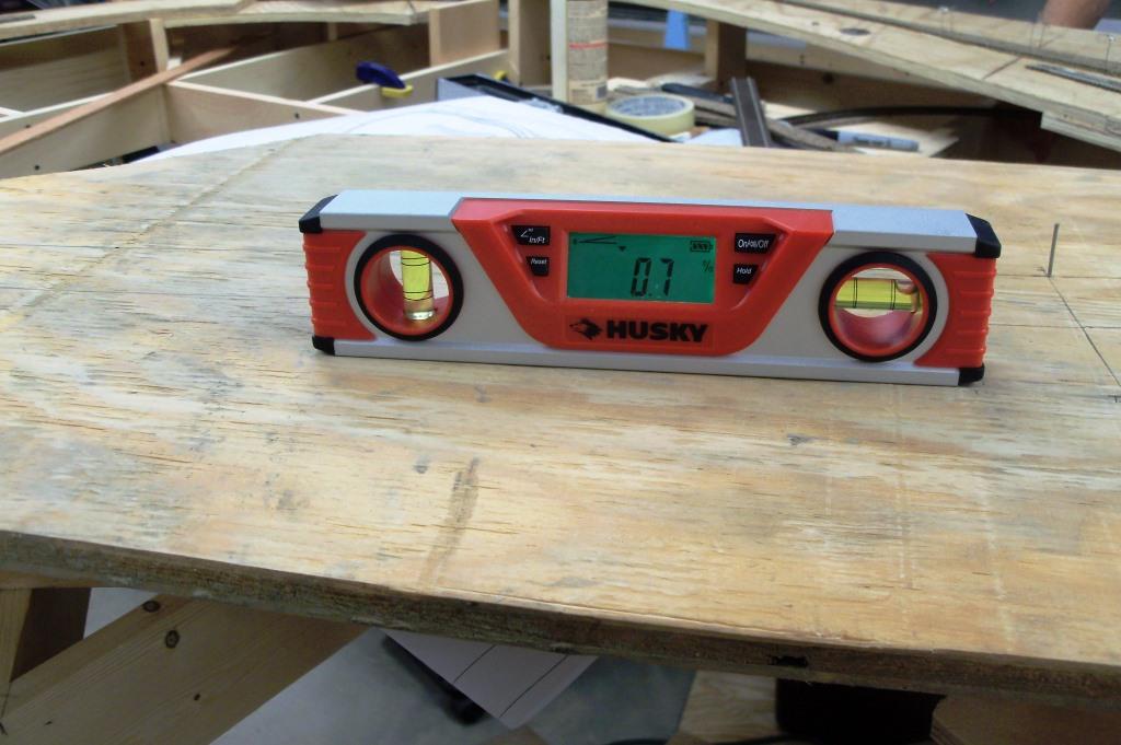
We tried out our new electronic level to roughly set the slope of the sub-roadbed (I'll still rely on the surveyor's level any day). We backed off to about 0.5% in the tangent section, as the steeper the grade here, the grade down to the helix turnout must be even steeper.
|
Risers were cut and screwed into place.
|
And the cardboard curve template was used to cut a plywood section of sub-roadbed through Wilkinsburg.
|
Jerry made temporary risers to demonstrate the grade through Wilkinsburg and clamped them in place, along with strips of Masonite for a temporary backdrop.
|
A small "shelf" was trimmed from the plywood to represent Finance Street, which parallels the tracks through Homewood, but at a lower elevation. The Walthers stamping plant kit will represent National Biscuit Company.
|
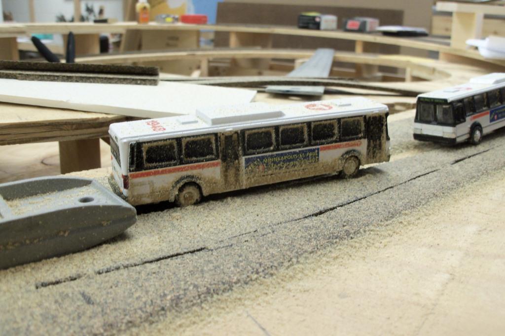
The buses staged on the East Busway took a lot of sawdust, which looked like winter slush clinging to their sides!
|
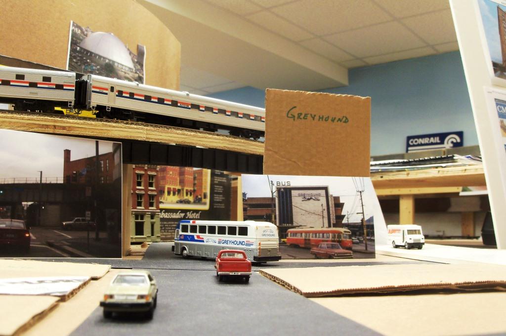
The night before the open house, we finalized a street plan for downtown Pittsburgh, concentrating on Penn and Liberty Avenues, and cut some cardboard footprints for the structure kits we plan to use. We then staged some vehicles and the Broadway Limited passenger train at the station. Several photos show the intended scene.
|
This scene closely matches a photo of the main line looking towards the Allegheny River at 11th Street.
|
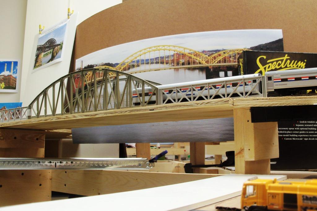
The Atlas curved chord truss bridge will represent the PRR Ft. Wayne Bridge until time allows us to scratchbuild it.
|
November 2014
The progress continues...
Jerry and Dan add some cross-members to the bench work where risers can be attached.
|
Jerry installs risers through Wilkinsburg.
|
Kevin Sapanara has joined our work crew. We met at an NMRA meeting last fall and spent some time together at this year's Cleveland Convention.
|
Kevin and Charlie work together laying track on helix #2.
|
The Pittsburgh station tracks are installed. The two tracks on the left are mainline through tracks, while the three on the right are stub-end station tracks.
Bob takes a breather from surveying riser elevations...
|
...and Andy installs some framing to support the backdrop at Swissvale.
|
Dan test fits a triangular cardboard template he cut to provide a base for industries in East Liberty.
|
A perfect fit!
|
Through September 2015
I have been reminded that there have been no progress updates for eight months, so allow me to fill you in. We accomplished some progress last spring, and after taking the summer off, are again back in a routine of working on the layout. Here is what we have gotten done so far in 2015.
~ Andy
~ Andy
We have nearly all the track in place through Shadyside and the wye at East Liberty. The LH turnout here will service the Nabisco plant.
|
Jerry made card stock mock-ups of a scaled down version of Walther's Miranda's Bananas for the Strip District.
|
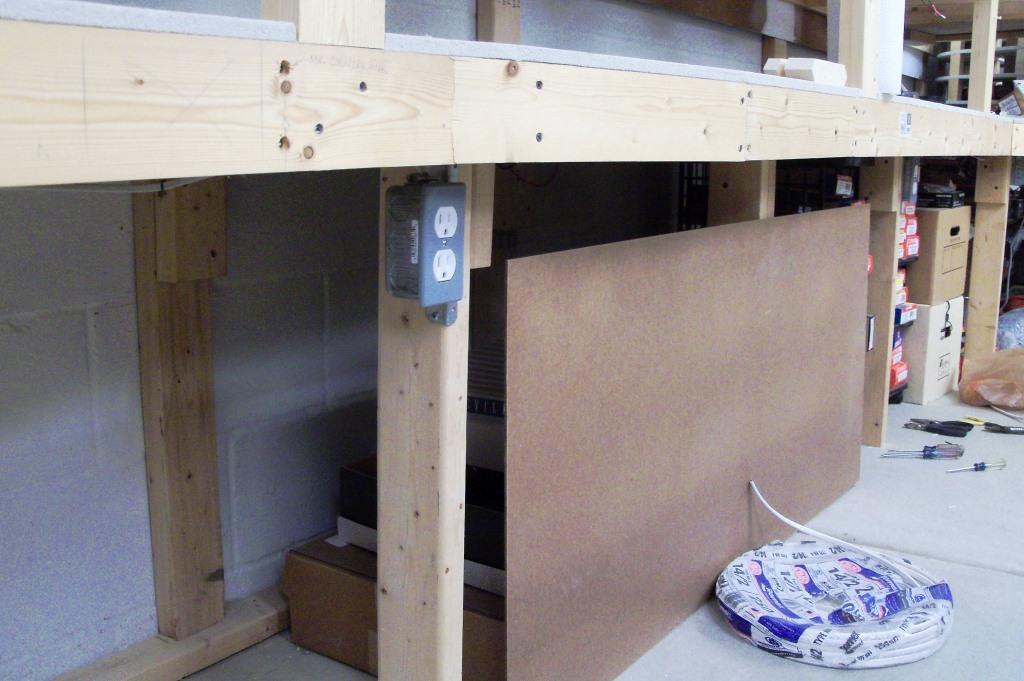
Bob installed electrical outlets below the bench work to supply work tools with power. All of the outlets will be controlled by a single switch and pilot light.
|
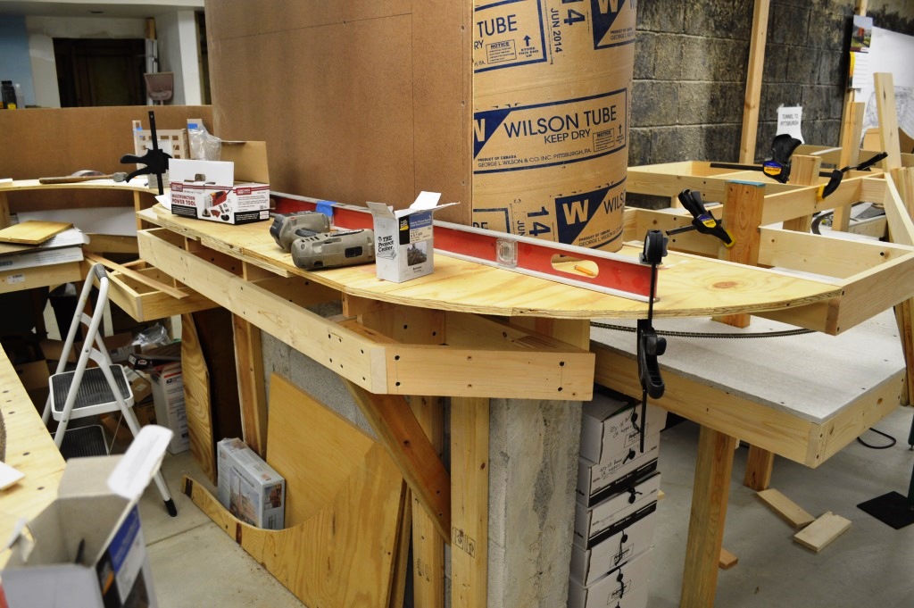
The masonite backdrop behind Union Swith & Signal in Swissvale and a 180-degree turn made from a 14-inch diameter concrete tube form are in place.
|
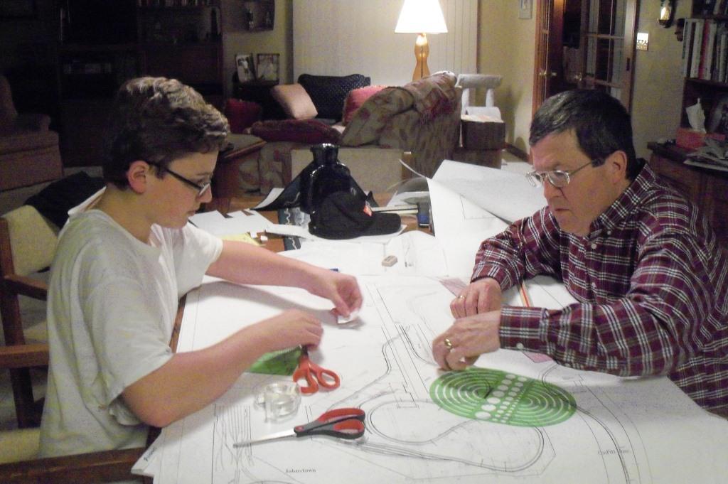
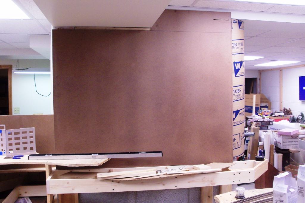
We realized that as we turned the corner into the new room, we needed to determine whether the Conrail mainline would run in front of or behind the steel mill, so we got out the drawing instruments, scales and pencils.
|
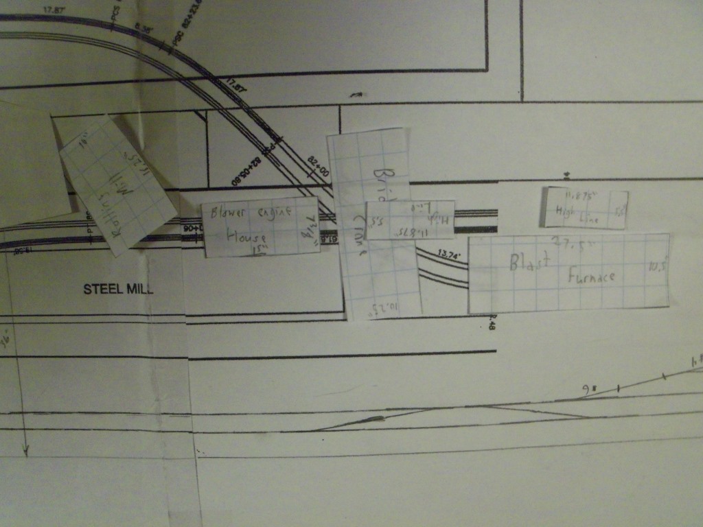
Charlie made scale footprints of the Walthers steel mill kits to see how they would fit together to represent USS Edgar Thomson Works. Ultimately, we decided to run the main line in front of the mill.
|
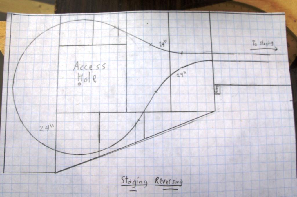
As we looked at the curvature of the track between Swissvale and Braddock, it became obvious that there was enough room for a 24-inch dia. reversing loop in staging, so Charlie drew it to scale and planned bench work.
|
It was a simple matter to install a #6 turnout on one of the main line tracks in staging followed by a second turnout to serve as a wye. The length of the reversing loop will accommodate a 14 foot train.
|
This photo shows the start of the reversing loop coming out of the existing staging track.
|
A short "connector" section of bench work was built...
|
...and the bench work for the reversing loop was installed and leveled.
|
Since strength was not an issue, we used some remaining Micor material (similar to Homosote) for the sub-roadbed.
|
We had the foresight to design an access hole in the middle of the reversing loop, which will be needed if there is ever a derailment.
|
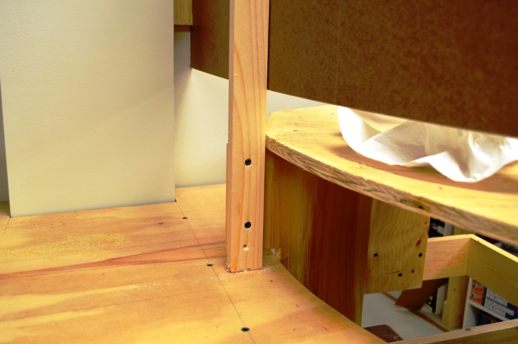
Next, a mirror image section of bench work was built for the upper level railroad. Here it is leveled up before attaching to the legs.
|
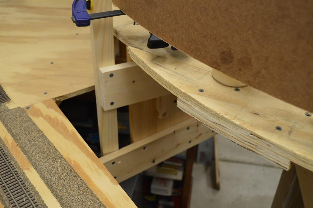
Although we don't plan to have a lift-out panel in Braddock, an access hole was also placed in the upper bench work to allow for backdrop construction.
|
The sub-roadbed was installed through Swissvale and backdrop screw holes filled with water putty.
|
Here the curve is obvious as the tracks pass Swissvale and round the curve to Braddock. The aisle to access Wilkinsburg will be narrow - just 28 inches wide.
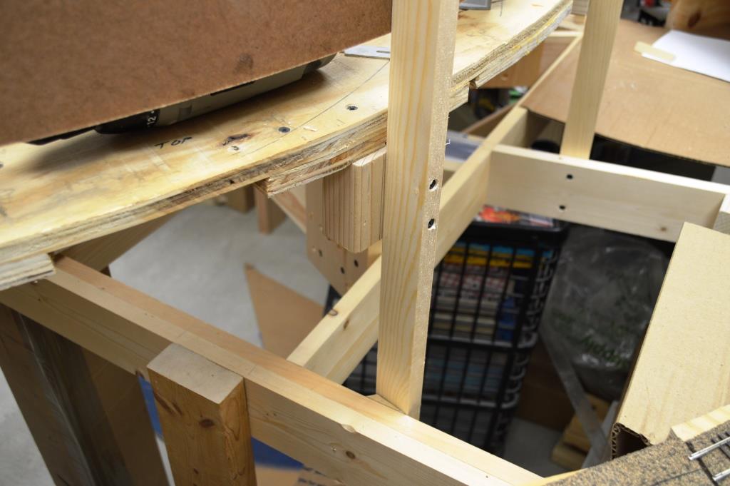
|
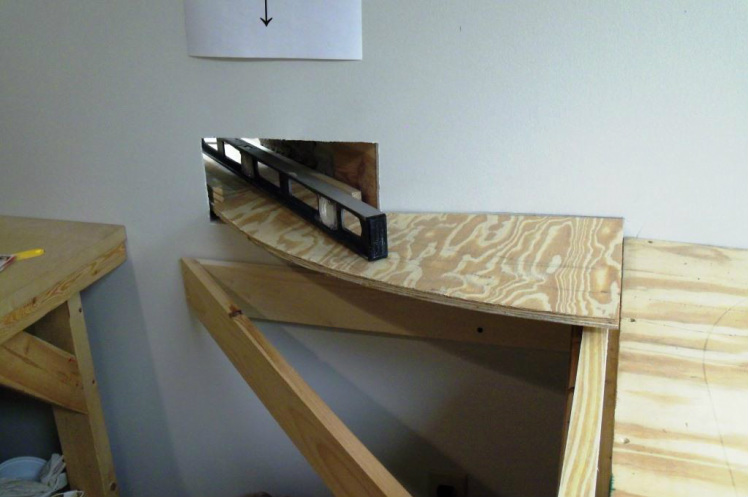
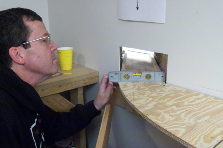
We test fit a piece of masonite to determine what was a reasonable position for the backdrop. With more than four feet from the front of the layout to the wall, more than an arm's reach would not be possible.
|
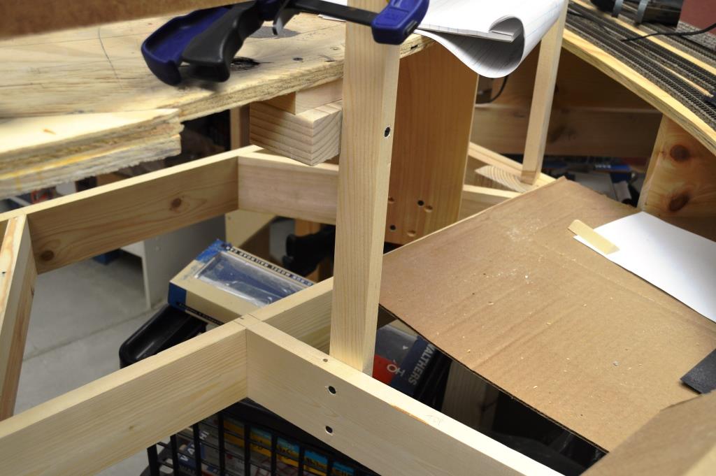
We decided that 36 inches was about as far as one could reach and so set out to build a false wall to support the backdrop.
|
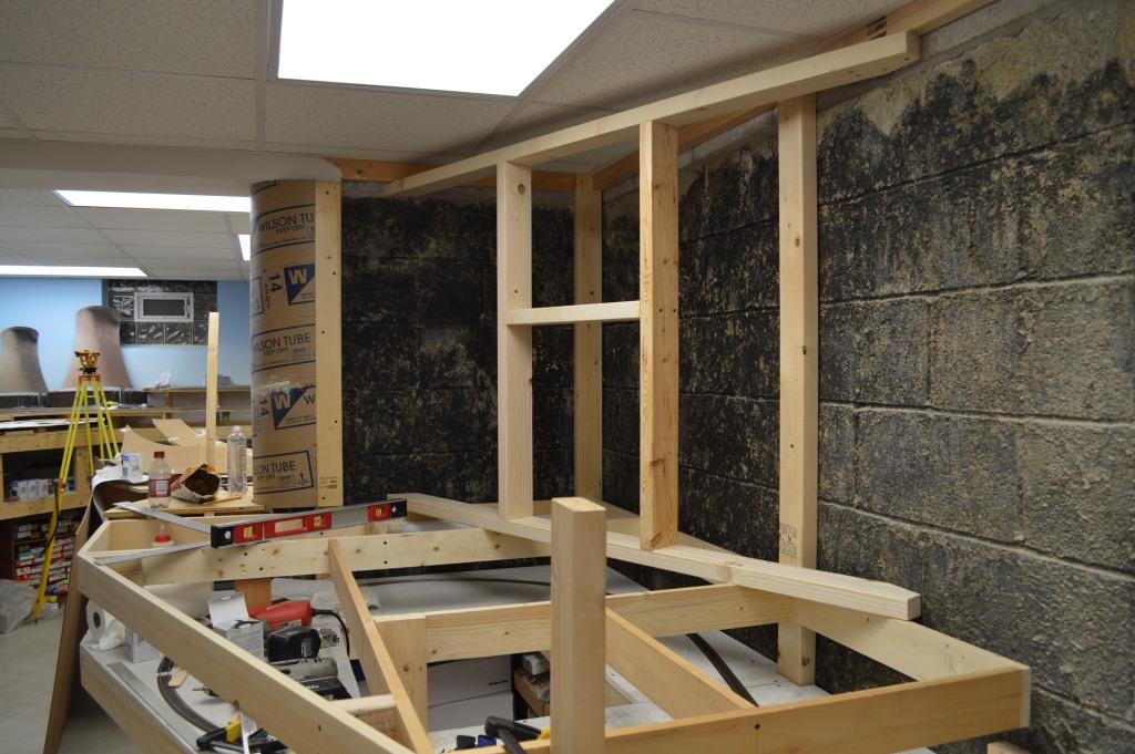
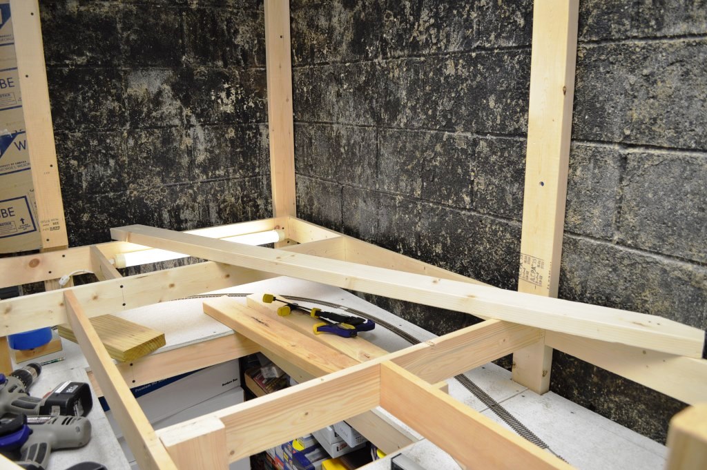
In addition to a horizontal 2x4 top and bottom, we built vertical framing shaped like the letter "H" to provide support for the backdrop.
|
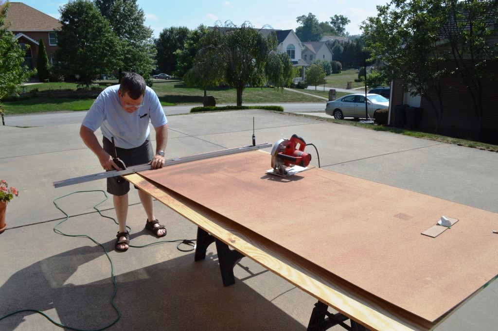
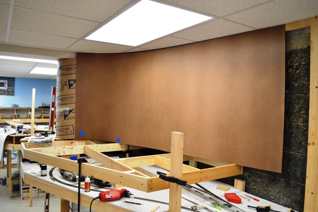
The initial portion of the backdrop was going to require a pretty severe curve; more than the 1/8" masonite would allow. Therefore, we cut a number of vertical grooves on the backside of the masonite so it would bend easier.
|
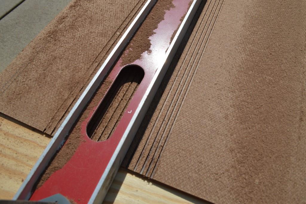
We used a 6-foot steel level as a guide for the circular saw, making cuts about half the thickness of the masonite every 3/8". Be prepared to replace the blade in your circular saw after this. We made about 40 cuts and trashed a blade.
|
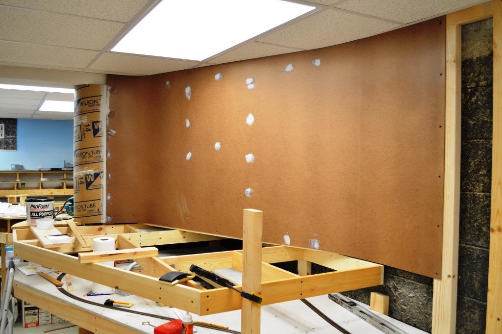
Here is the finished backdrop section affixed in place to the framing. We tried Bondo as joint filler between the masonite and concrete form tube.
|
The sharp curve on the left is why we had to cut the vertical grooves. Also visible is a fluorescent light we installed to illuminate the reverse loop.
|
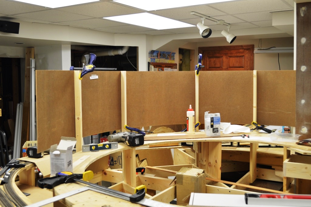
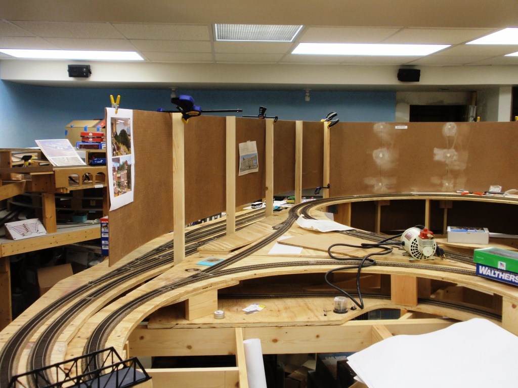
Next it was time to turn our attention to the permanent free-standing backdrop between Pittsburgh and Wilkinsburg. We affixed 1x2's vertically to support a piece of masonite backdrop on both sides.
|

Wilkinsburg is six to eight inches higher that Pittsburgh, which required two connection points for each vertical riser, but also added stability.
|
We quickly realized that each support would be unique as to how it was attached. Here we added an extra riser.
|
While here we could piggyback onto an existing riser for the second support.
|
Existing bench work provides a connection point at the bottom of the third support, while a short piece of 2x4 was added to the sub-roadbed above.
|
A similar approach worked for the fourth support.
|
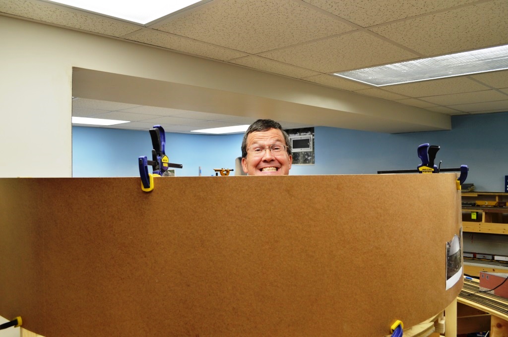
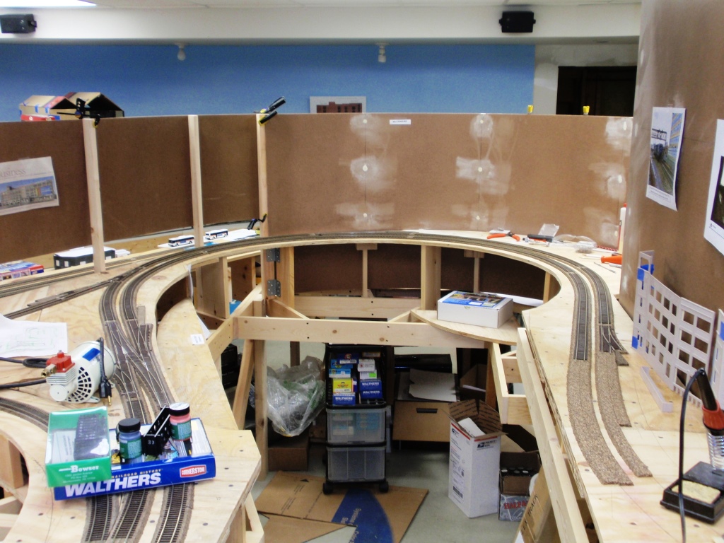
After much debate, we settled on a backdrop height of 5 feet, 4 inches. This is high enough to block your view of the layout, but low enough to allow conversations and visual contact between operators.
|
Here is the backside of the temporary backdrop as viewed from Wilkinsburg. A second sheet of masonite will be added to this side.
|
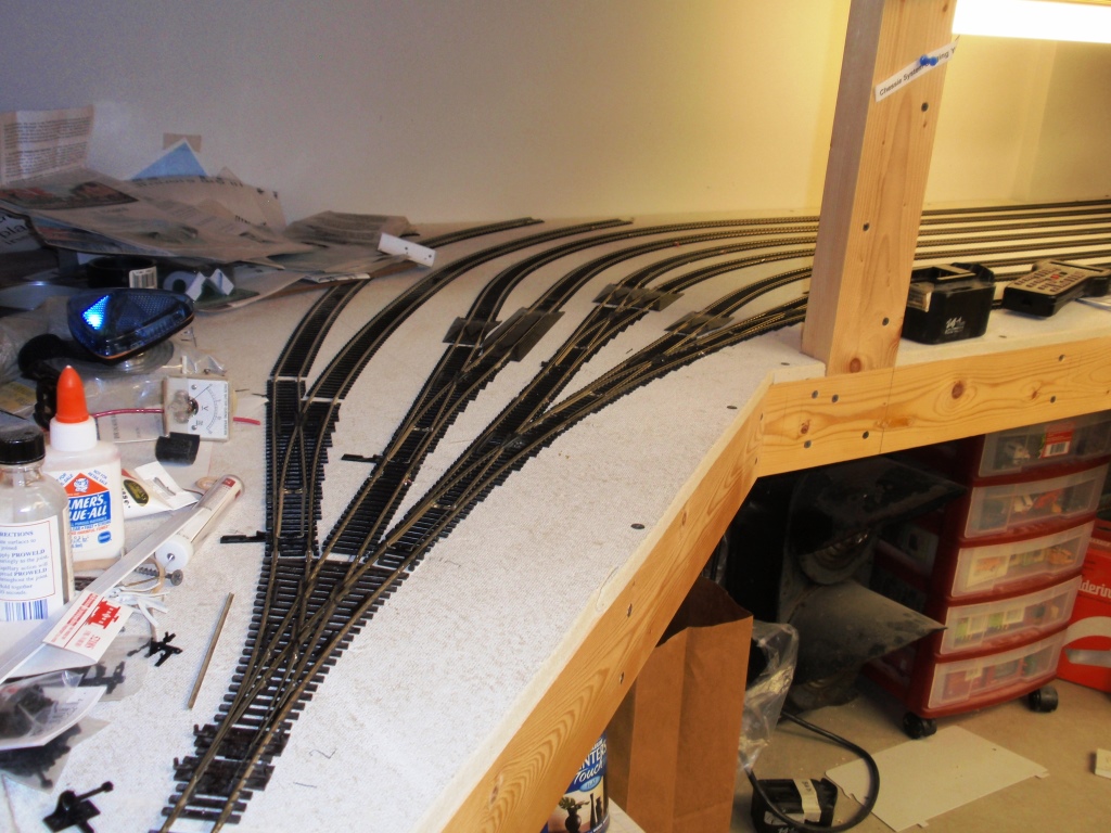
Although the track had been constructed years ago, the wye in staging, leading to the Chessie System staging yard, had never been wired. So, in hopes of having the Chessie System portion of the layout operable in the near future, we wired up the wye with a PSX-AR auto reverser.
|
The wye leads to the Chessie staging yard in the bottom right corner. The Chessie main along with both Conrail mains enter the helix in the top right and Conrail staging is off to the left.
|
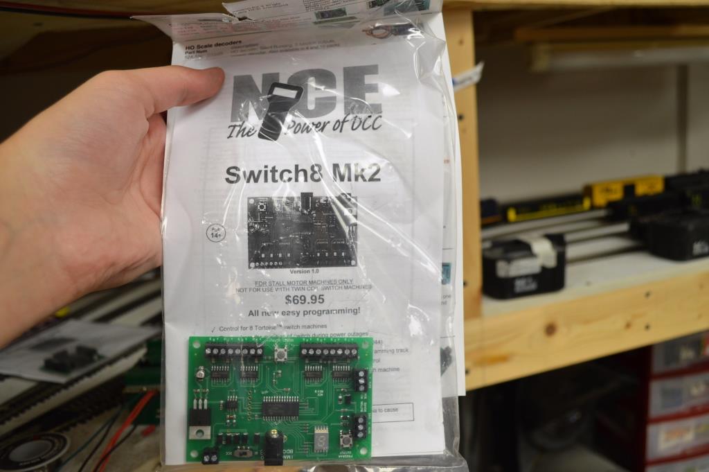
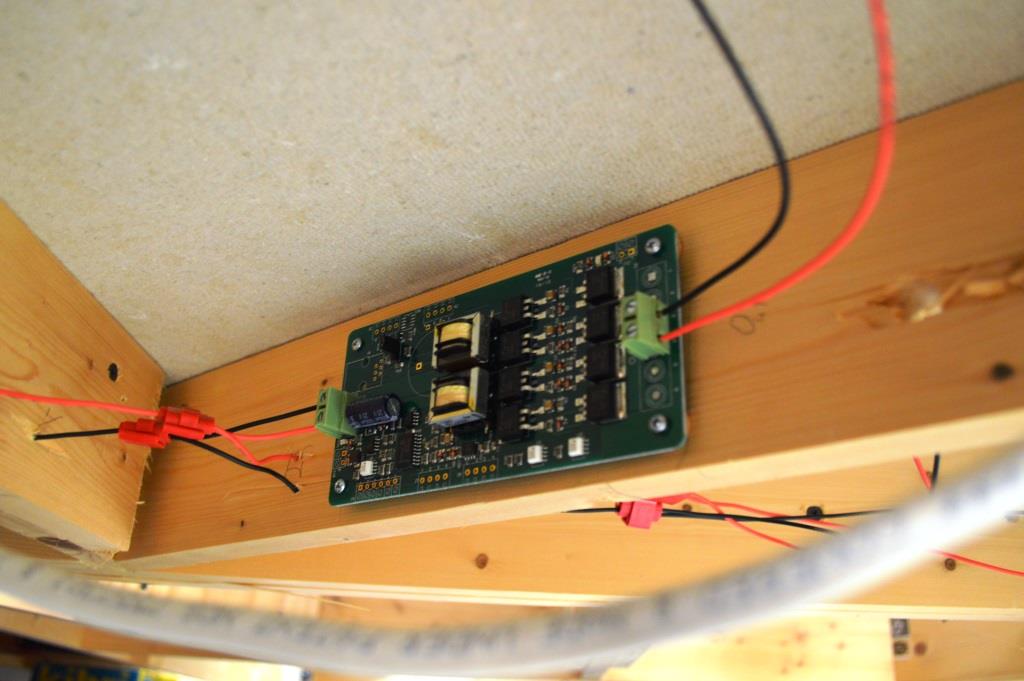
We have chosen to use commercially available circuitry from NCE for powering and controlling the Tortoise Switch machines in the Chessie Staging yard. The Switch8 Mk2 is capable of controlling eight Tortoises, using a DCC Thottle to throw them.
|
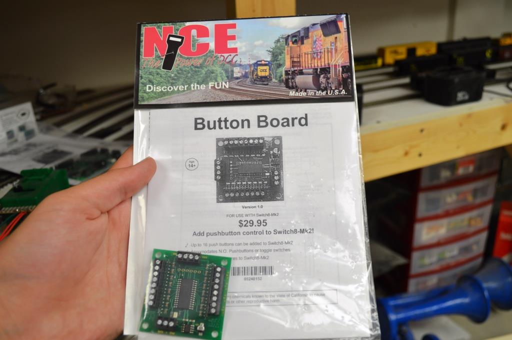
We would like the Tortoises to be controlled by push buttons though, so we also purchased the NCE Button Board. If we like this method, we will use it on the second Conrail staging yard as well.
|
October 2015
With another NMRA meeting and open house this month, we really made a push to get work done on 10/2/2015. Here are some photos.
Charlie's best work is sometimes invisible! He has installed and wired all the switch motors in the Chessie staging yard, including powering each frog. He has also hooked each switch motor to the NCE circuit board, each with an assigned address. Operation here is flawless now.
|
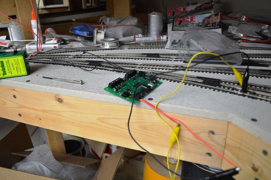
He first tested and programmed each Tortoise switch machine before installing. Here he uses alligator clip test leads to connect the Switch8 Mk2 board to track power.
|
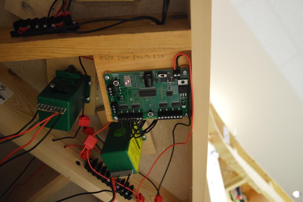
With all the switch machines tested and programmed, the Switch8 circuit board was mounted beneath the benchwork. For now, we will control turnouts with our throttles, but we will eventually create a switch diagram with push buttons for the fascia panel.
|
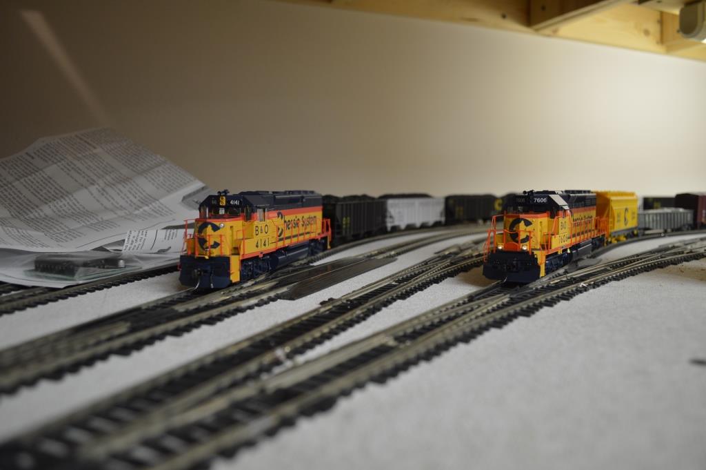
The power was turned on and the turnout points lined up, all using a DCC wireless throttle. The Chessie staging yard was now operational.
|
Charlie gave me the honor to bring the first train out of the Chessie staging yard and up the helix.
|

Work continued on the backdrop. We initially countersunk screws in the Masonite, but found that filling the screw holes to achieve a smooth finish was difficult and time consuming. We eventually went with gluing the Masonite to the vertical supports and clamping overnight as shown here.
|

This view shows the construction method for the backdrop. More on this later - we learned a lot and improved as we went. With both sides attached, this free-standing section is quite strong.
|
All track has been installed in and through Shadyside and East Liberty.
|
Looking a bit like Horseshoe Curve, it is really just the bend through Wilkinsburg. The building front on the right will be the location of Union Switch & Signal.
|
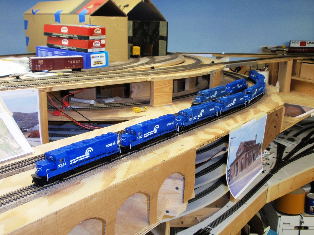
Apparently a power redistribution move passing through Johnstown.
|
Bruce and Dan took on the task of constructing sub-roadbed for the Strip District and installing risers to the proper elevation.
|
The finished section will give us room for 2 or 3 industries to be served by Allegheny Valley Railroad.
|
A quick break to admire their work...
|
We also decided to add a small extension to downtown Pittsburgh by building into the aisle way just a bit.
|
This adds about four inches to the benchwork and will allow a few more buildings to be modeled in Pittsburgh.
|
Meanwhile, sawdust was flying in the new room as Dan, Kevin and Charlie built the next section of benchwork to extend through Braddock. Work space looks a little cramped.
|
We always try to be safe when using the power tools, as Charlie demonstrates.
|
No one can accuse Dan of not being precise!
|
The benchwork section was leveled and fastened to the wall. Temporary front legs/risers were installed.
|
For the open house, we set out some building kits and equipment to suggest the future site of Edgar Thomson Works steel mill.
|
This photo shows our support framing method for the Masonite backdrop. The vertical 2x4s are screwed into the sill plate at the top, then held tight to the wall with a single Tapcon anchor. They are placed on four foot centers.
|
Horizontal members, three in each panel, are cut to be a press fit, then glued in place with Gorilla Glue, here seen oozing out of the joint. Once dry, a paint scraper takes off the excess in a jiffy. The top horizontal member also provided a wood mounting surface for the suspended ceiling perimeter "L" channel.
|
December 2015
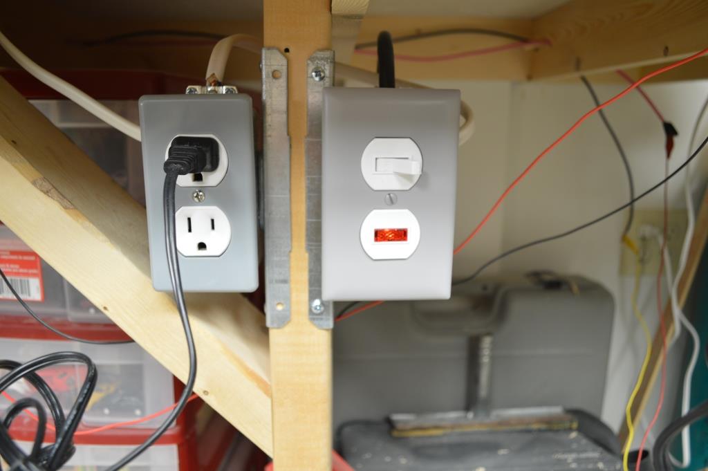
A switch and indicator light were installed at the beginning of the power outlets that have been run for the layout. This allows an easy way to turn off layout power and to see if the power is still on when you leave the room.
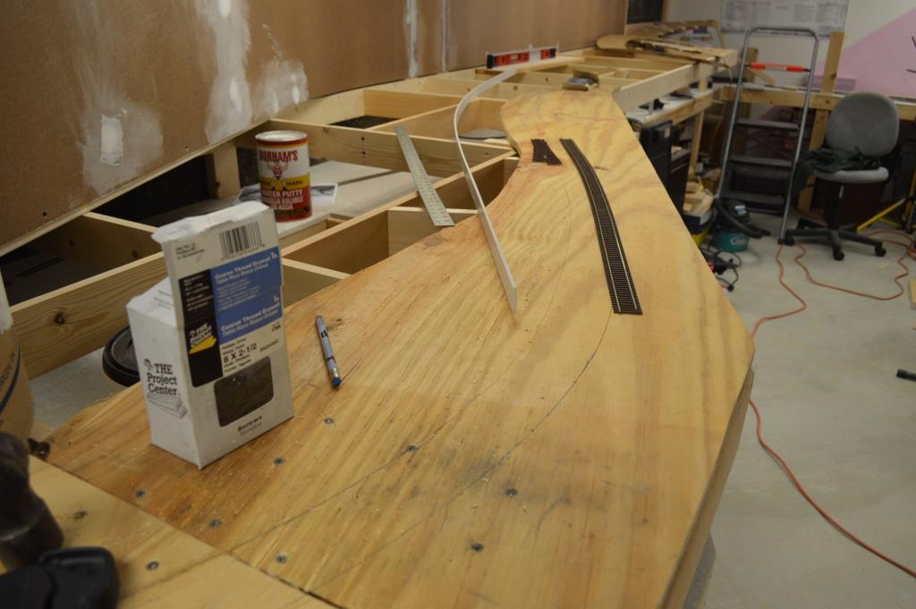
Plywood was cut for the track entering the new room towards Braddock. A gentle S bend with the track has been drawn which will give a very realistic look. The mainline will continue to climb as the scenery behind it stays mostly level, so it will require two pieces of plywood (one for track and one behind it for Braddock Ave.
|
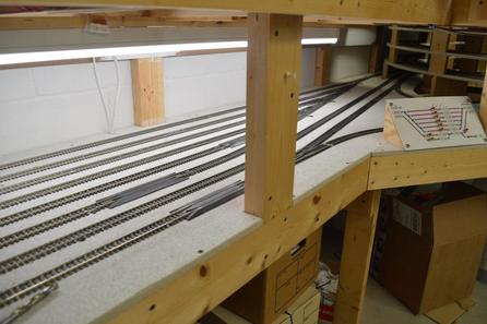
Several four foot LED lights were added above Conrail's eastbound staging yard to allow for a better view of trains traversing the yard ladder.
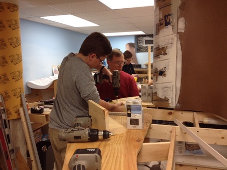
Charlie and Dan work on the splice for the plywood.
|
We braced and plumbed the support legs under westbound staging in advance of adding the upper level bench work. Here Bruce levels a section to measure for an additional leg on a particularly long span.
|
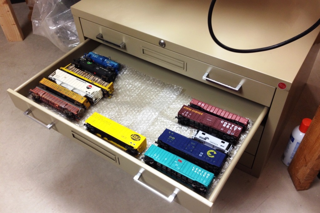
A friend from our church offered us a flat drawer file unit , which we readily accepted. We saw its potential for storing rolling stock. A piece of bubble wrap on the drawer bottoms helps protect the cars.
|
And that pretty much wraps up 2015. We are going to start a new page for our second decade of progress, which we will arrange like a blog page, putting the most recent entries at the top. This will eliminate the need to scroll to the bottom to check for updates.
